Virtual reality display device and equipment and sight angle calculation method

A display device and virtual reality technology, applied in computing, computer parts, input/output of user/computer interaction, etc., can solve the problems of poor imaging quality, high cost, high viewing angle and size requirements of infrared cameras, and reduce the viewing angle. and size requirements, the imaging angle and quality are excellent, and the effect of avoiding shooting blind spots

Active Publication Date: 2018-09-11
BOE TECH GRP CO LTD +1
View PDF5 Cites 7 Cited by
  • Summary
  • Abstract
  • Description
  • Claims
  • Application Information

AI Technical Summary

Problems solved by technology

[0003] The current VR devices usually have the eye tracking function. The infrared camera is set on the side of the VR device close to the user to directly or indirectly capture images of the user's eyes to obtain the pupil position. However, in order not to affect the user's line of sight, the position of the infrared camera needs to be Far away from the user's line of sight, there are high requirements for the viewing angle and size of the infrared camera, high cost, and poor imaging quality

Method used


Image

  • Virtual reality display device and equipment and sight angle calculation method
  • Virtual reality display device and equipment and sight angle calculation method
  • Virtual reality display device and equipment and sight angle calculation method

Examples


Embodiment Construction

[0037] In order to illustrate the present invention more clearly, the present invention will be further described below in conjunction with preferred embodiments and accompanying drawings. Similar parts in the figures are denoted by the same reference numerals. Those skilled in the art should understand that the content specifically described below is illustrative rather than restrictive, and should not limit the protection scope of the present invention.

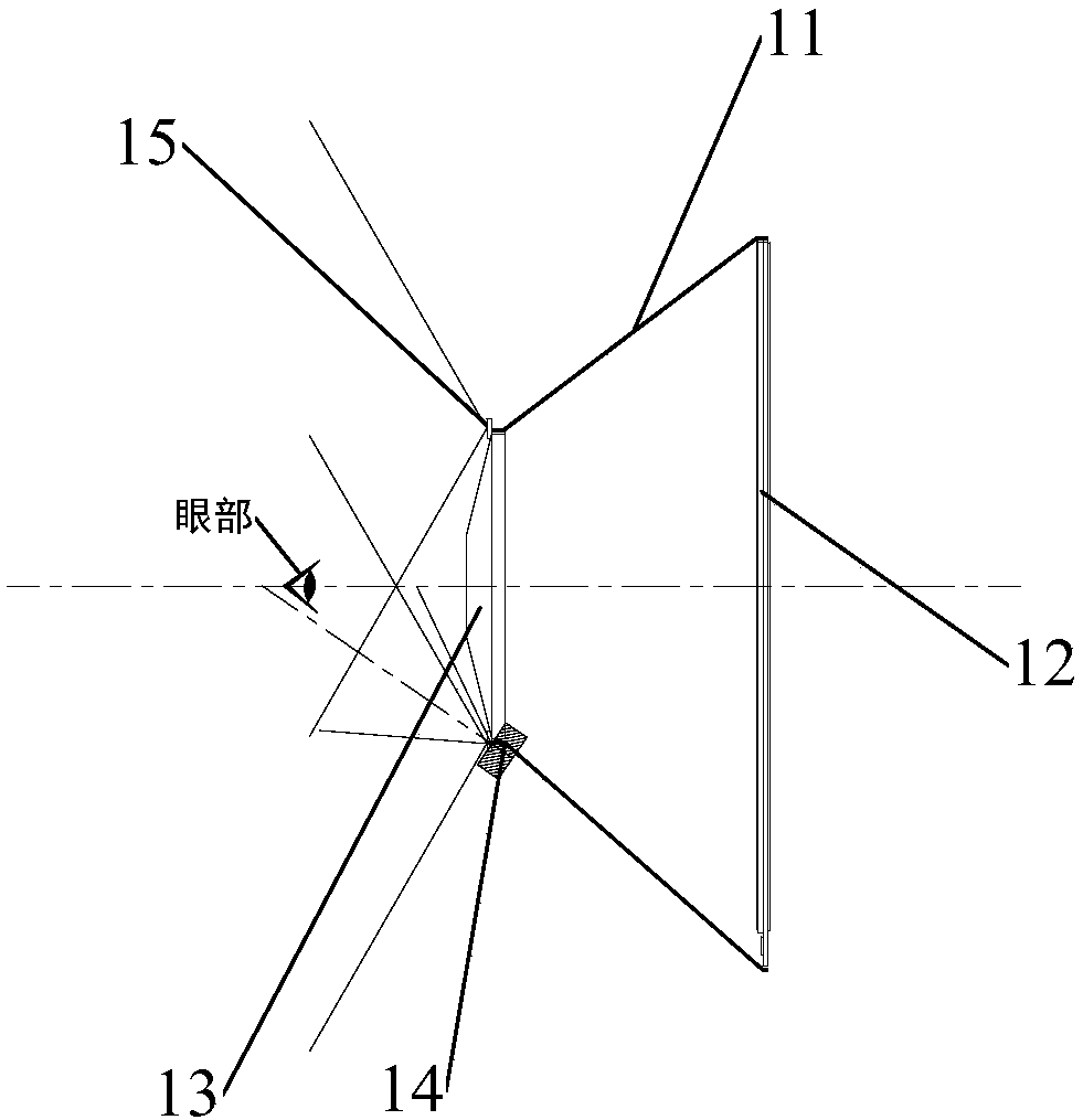
[0038] figure 1 A schematic diagram showing a virtual reality display device in the prior art. Such as figure 1 As shown, in the prior art, a virtual reality display device includes a lens barrel 11 and a lens 13 and a display screen 12 arranged on both sides of the lens barrel 11, and the picture displayed on the display screen 12 is imaged in the eyes of the user through the lens 13, so that the user can View the content displayed on the display screen 12.

[0039] In order to realize the eye tracking function of the ...


PUM


Abstract

The invention discloses a virtual reality display device. The device comprises a display screen for displaying a frame to a user, at least one infrared light source and an infrared camera; the infrared camera is arranged at the side, away from the eyes of the user, of the display screen and used for collecting an eye image of the eyes of the user under the irradiation of at least one infrared light source. The invention further discloses a sight angle calculation method and display equipment comprising the virtual reality display device. The requirement of the infrared camera for the eyeball tracking function of the display device is lowered, and therefore the cost is lowered; the eyeball imaging quality is improved, a photographing blind region is avoided, and then the eyeball tracking precision is improved.

Description

technical field [0001] The invention relates to the field of display technology. More specifically, it relates to a virtual reality display device, equipment, and a method for calculating a viewing angle. Background technique [0002] Virtual reality (Virtual Reality, VR) technology is a virtual environment based on immersion and conception, using computer technology as the core and relying on graphics and image processing means to simulate human vision, hearing and Touch and so on get the same feeling as the real world. [0003] The current VR devices usually have the eye tracking function. The infrared camera is set on the side of the VR device close to the user to directly or indirectly capture images of the user's eyes to obtain the pupil position. However, in order not to affect the user's line of sight, the position of the infrared camera needs to be Far away from the user's line of sight, the infrared camera has high requirements on the viewing angle and size, high ...

Claims


Application Information

Patent Timeline
Patent Type & Authority Applications(China)
IPC IPC(8): G06F3/01G06K9/00G06K9/20G06V10/143
CPCG06F3/013G06V40/19G06V10/145G06V10/22G06F3/011G02B27/0093G06V10/143G06T7/73G06T2207/10048G06T2207/30201G02B27/0172G02B2027/0138H04N23/56H04N23/57G06T7/70G02B3/0006
Inventor 马占山田文红王晨如张浩井颢然孙志宇郑超赵斌葛峥
Owner BOE TECH GRP CO LTD
Why Eureka
Try Eureka