Liquid crystal display device

a liquid crystal display and display device technology, applied in the direction of instruments, polarising elements, optics, etc., can solve the problems of poor symmetry, light leakage, and the inability to obtain the desired viewing angle characteristic,

Active Publication Date: 2005-07-07
HANNSTAR DISPLAY CORPORATION
View PDF3 Cites 13 Cited by
  • Summary
  • Abstract
  • Description
  • Claims
  • Application Information

AI Technical Summary

Benefits of technology

[0015] In view of the above-mentioned problems in the conventional liquid crystal display devices, it is an object of the present invention to provide a liquid crystal displa

Problems solved by technology

The above-mentioned liquid crystal display device suggested in Japanese Patent Application Publication No. 1-270024A is accompanied with a problem of poor symmetry in contrast, and the liquid crystal display device suggested in Japanese Patent Application Publication No. 2000-29010A improves symmetry in contrast, but is accompanied with a problem that light is leaked when a viewer varies a viewing angle from a direction in which a normal line of a substrate extends.
The liquid c

Method used


Image

  • Liquid crystal display device
  • Liquid crystal display device
  • Liquid crystal display device

Examples


first embodiment

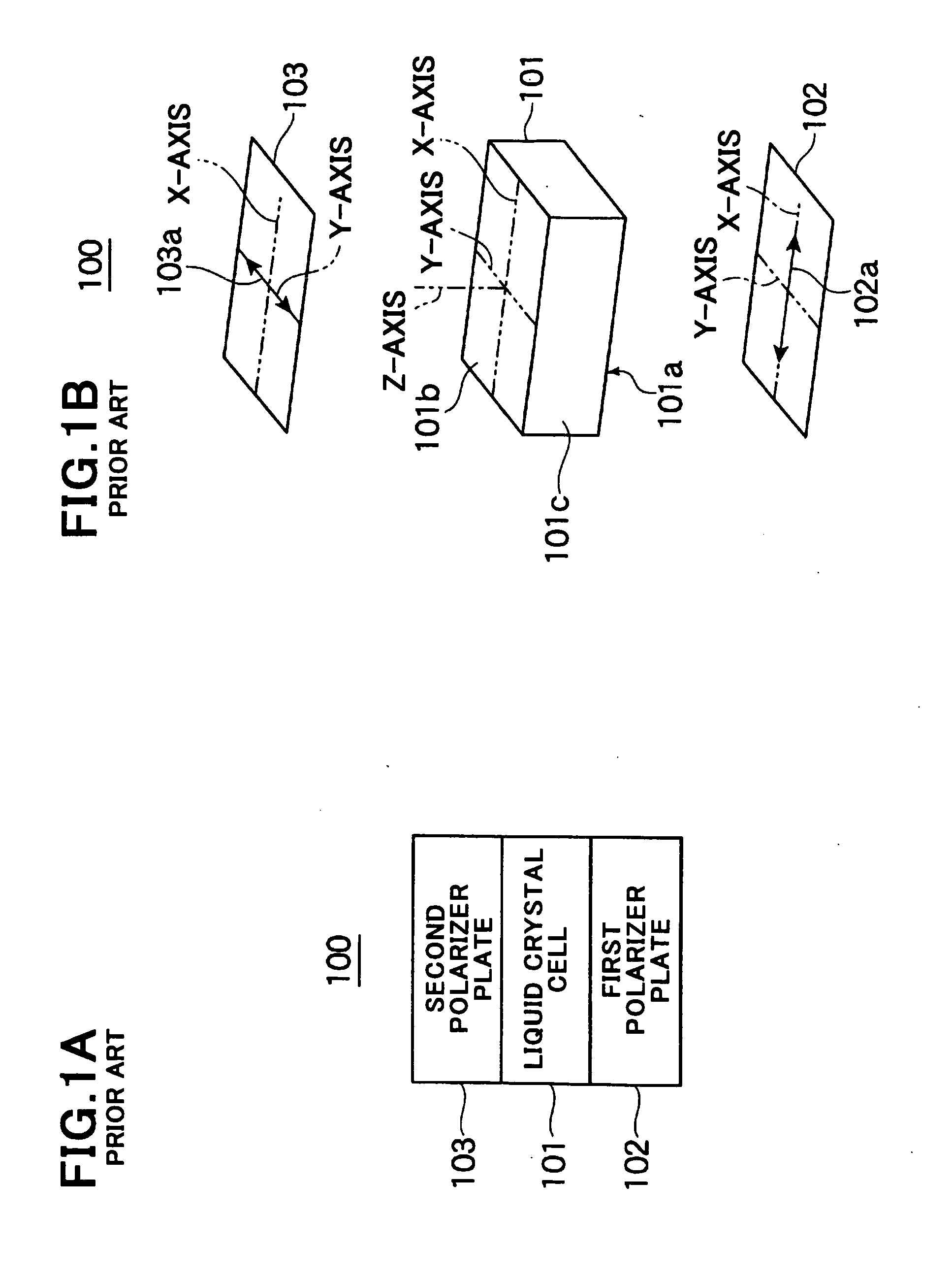
[0162]FIG. 20A is a front cross-sectional view illustrating a layered-structure of a liquid crystal display device 1 in accordance with the first embodiment of the present invention, and FIG. 20B is a broken perspective view of the liquid crystal display device 1.

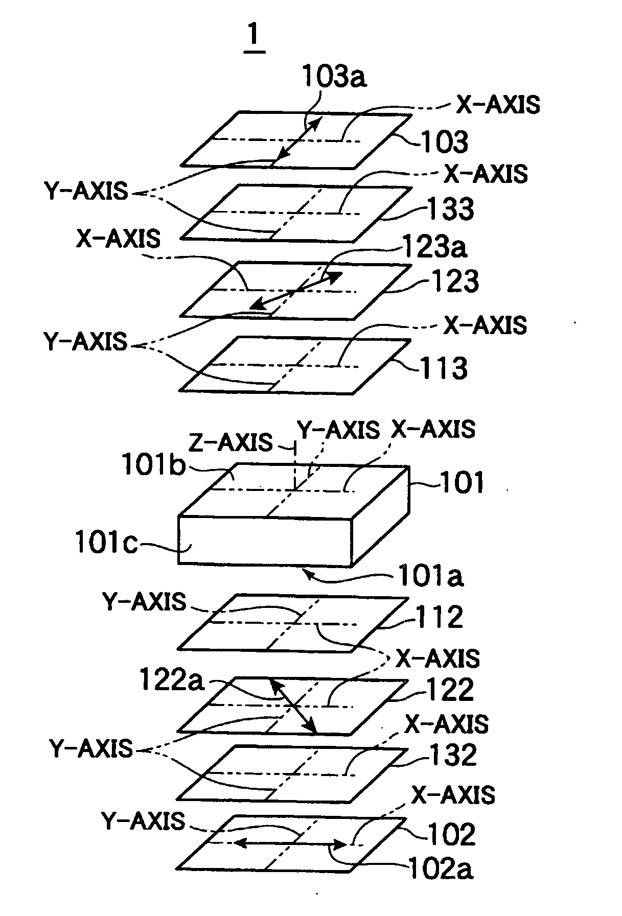
[0163] As illustrated in FIG. 20A, the liquid crystal display device 1 is comprised of a liquid crystal cell 101 including vertically aligned liquid crystal, a first polarizer plate 102 arranged on one of surfaces of the liquid crystal cell 101, a second polarizer plate 103 arranged on the other surface of the liquid crystal cell 101, a first λ / 4 plate 122 arranged between the liquid crystal cell 101 and the first polarizer plate 102, a second λ / 4 plate 123 arranged between the liquid crystal cell 101 and the second polarizer plate 103, a first optical compensation layer 112 arranged between the liquid crystal cell 101 and the first λ / 4 plate 122, and having negative uniaxial retardation, a second optical compensation laye...

second embodiment

[0233]FIG. 40A is a front cross-sectional view of a liquid crystal display device 10 in accordance with the second embodiment of the present invention, and FIG. 40B is a broken perspective view of the liquid crystal display device 10.

[0234] As illustrated in FIG. 40A, the liquid crystal display device 10 in accordance with the second embodiment is designed not to include the second optical compensation layer 113 in comparison with the liquid crystal display device 1 illustrated in FIGS. 20A and 20B. The liquid crystal display device 10 in accordance with the second embodiment has the same structure as that of the liquid crystal display device 1 except in not including the second optical compensation layer 113.

[0235] The first and second polarizer-supports 132 and 133 in the second embodiment have retardation of 25 nanometers in a thickness-wise direction thereof.

[0236] The inventors tested viewing angle characteristic in six liquid crystal display devices each of which had the sa...

third embodiment

[0251] In the above-mentioned first and second embodiments, a liquid crystal cell allows a light to pass therethrough. In the third embodiment explained hereinbelow, a liquid crystal cell has a pixel electrode both having a first area in which a light is allowed to pass therethrough, and a second area in which a light is reflected.

[0252]FIG. 53 is a perspective view of a liquid crystal cell 53 in a liquid crystal display device in accordance with the third embodiment, and FIG. 54 is a plan view of the liquid crystal cell 53. For simplification, general parts constituting a liquid crystal display device, such as a thin film transistor (TFT) and a wiring electrode, are omitted in FIGS. 53 and 54.

[0253] As illustrated in FIGS. 53 and 54, the liquid crystal cell 53 is of so-called half-transmission type, that is, the liquid crystal cell 53 has a pixel electrode 101e comprised of a transparent electrode 532 in which a light is allowed to pass therethrough, and a light-reflection electr...


PUM


Abstract

A liquid crystal display device includes a liquid crystal cell, first and second polarizers disposed outside the liquid crystal cell, first and second retardation plates arranged between the first and second polarizers, and the liquid crystal cell, and optical layers arranged between the first and second retardation plates and the liquid crystal cell. The first and second retardation plates have lagging axes perpendicular with each other. The first polarizer has an absorption axis inclining by about 45 degrees relative to the lagging axis of the first retardation plate, and inclining by about 90 degrees relative to an absorption axis of the second polarizer. The absorption axes of the first and second polarizers are angularly deviated such that characteristic of a viewing angle in the liquid crystal display device is rendered symmetric, relative to a symmetry axis about which liquid crystal is aligned in different directions.

Description

BACKGROUND OF THE INVENTION [0001] 1. Field of the Invention [0002] The invention relates to a liquid crystal display device. [0003] 2. Description of the Related Art [0004] Japanese Patent Application Publication No. 1-270024A has suggested a liquid crystal display device comprised of a liquid crystal cell in which liquid crystal is vertically aligned, first and second polarizer plates arranged at opposite sides about the liquid crystal cell, a first λ / 4 plate arranged between the liquid crystal cell and the first polarizer plate, and a second λ / 4 plate arranged between the liquid crystal cell and the second polarizer plate, wherein “λ” indicates a wavelength of a light. The suggested liquid crystal display device improves viewing angle characteristic observed when a viewer obliquely views the liquid crystal display device. [0005] There has been developed a display presenting high visibility even under external light. For instance, Japanese Patent Application Publication No. 2000-2...

Claims


Application Information

Patent Timeline
IPC IPC(8): G02B5/30G02F1/1335G02F1/13363G02F1/1337G02F1/139
CPCG02F1/1393G02F2413/14G02F2001/133638G02F1/133638G02F1/1335G02F1/1337
Inventor ISHII, TOSHIYASAKAMOTO, MICHIAKI
Owner HANNSTAR DISPLAY CORPORATION
Why Eureka
Try Eureka