
Pointer positioning device and method

a positioning device and pointer technology, applied in the direction of instruments, computing, electric digital data processing, etc., can solve the problems of complex image recognition process of display area detected by video cameras, limited to image display having synchronizing signals, and unable to perform cursor positioning functions through this method

Active Publication Date: 2007-11-29
PIXART IMAGING INC
View PDF5 Cites 13 Cited by
  • Summary
  • Abstract
  • Description
  • Claims
  • Application Information

AI Technical Summary

Benefits of technology

[0010]It is an object of the present invention to provide a pointer positioning device and method, which utilizes an auxiliary point generating a predetermined spectrum in cooperated with an image sensor integrated with an optical filter for pointer positioning, the device of the present invention can position an aiming point correctly disregard of a distance of the image sensor from the image display and a rotating angle of the image sensor during photographing.
[0011]It is another object of the present invention to provide a pointer positioning device and method, which utilizes an auxiliary point generating a predetermined spectrum in cooperated with an image sensor integrated with an optical filter for pointer positioning, since it is not necessary to photograph the whole display area of the image display, the viewing angle of the image sensor applied in the present invention can be decreased.

Problems solved by technology

However, in an image display without synchronizing signals, e.g. a liquid crystal display (LCD), a plasma display panel (PDP) and a projection screen, the cursor positioning function can hardly be performed through this method.
Therefore, the above mentioned method has the problem of being limited to the image display having synchronizing signals.
In practical use, although the method can be applied to any types of image display for playing shooting game with the photographic pointer positioning device not being limited by the type of image display, the image recognition process of the display area detected by video camera is still complicated.
The video camera has to detect the whole display area no matter which point is aimed by the photographic pointer positioning device, therefore the method still has the problem of needing a video camera with large viewing angle.
Although one reference signal is added to facilitate the processing of the image signal processed by an image processing unit, the aforementioned problems, i.e. difficult to recognize image display area and need a video camera with large viewing angle, are still left unsolved.
In addition, when an image sensor is utilized to photograph an image area, the photographing distance of the image sensor from the image area and the rotating angle of the image sensor during photographing may affect the positions of images formed on the sensing array of the image sensor.
If it is not adjusted, an error positioning of the aiming point may occur.

Method used


Image

  • Pointer positioning device and method
  • Pointer positioning device and method
  • Pointer positioning device and method

Examples


Embodiment Construction

[0035]First, it should be noted that in the following description of the present invention, similar elements are designated by the same reference numerals.

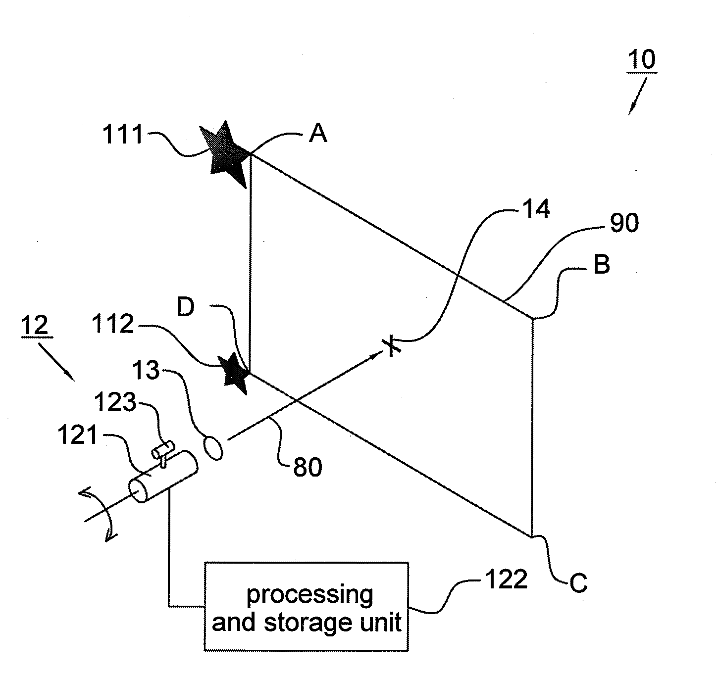
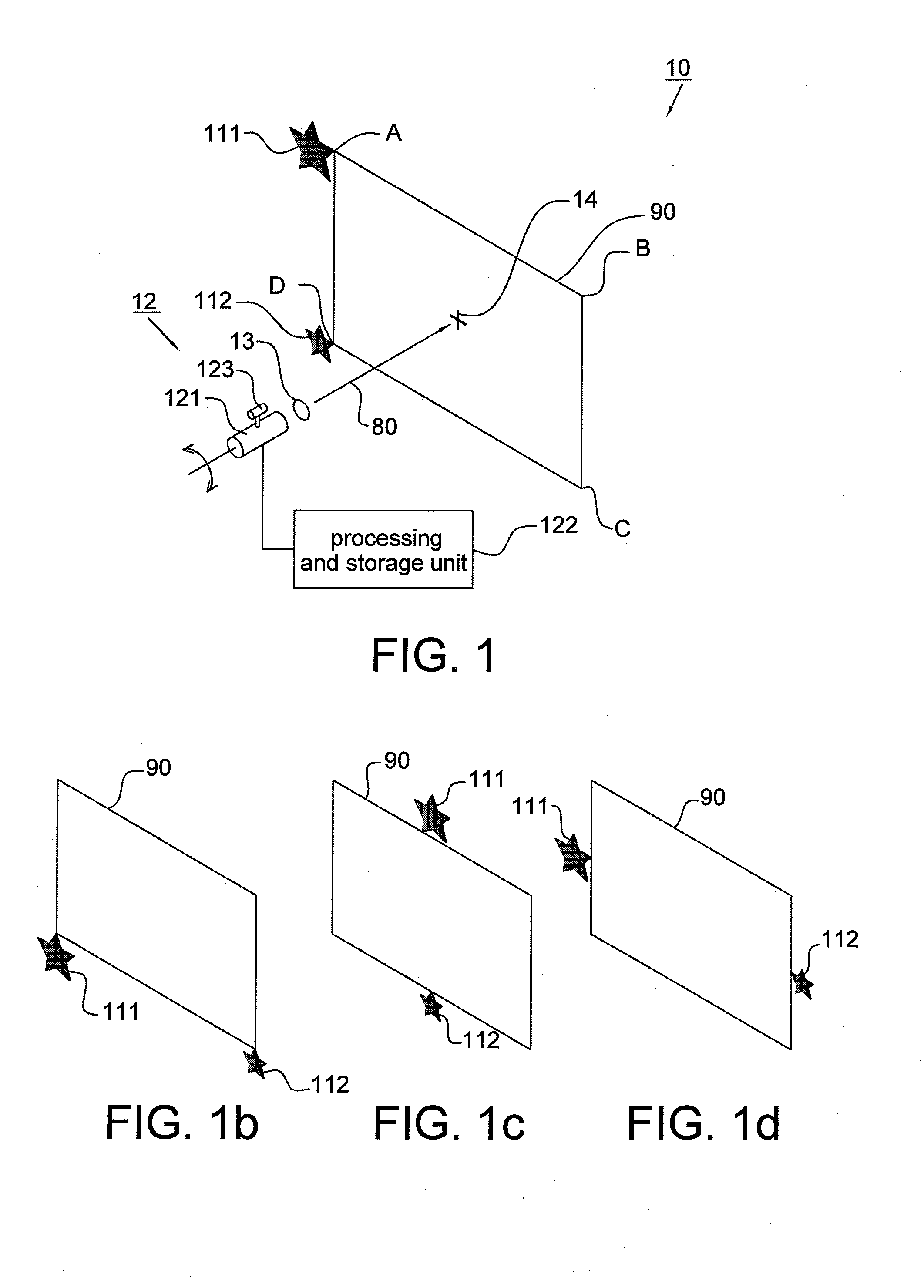
[0036]Referring to FIG. 1a, it shows a pointer positioning device 10 according to one embodiment of the present invention, which can be applied to position an aiming point on an image display, e.g. a projection device, a display of a game machine system or a display of a computer system. The image display has a display screen 90 for displaying image, e.g. the display screen 90 may be a part of or the whole image display area of a projection screen, a display screen of a game machine system or a display screen of a computer system, and “A”, “B”, “C” and “D” are four points on the display screen 90 or outside the display screen 90, e.g. four corners of the display screen 90 as shown in FIG. 1a. The four points form a quadrangle.

[0037]The pointer positioning device 10 includes two auxiliary points 111 and 112, an image sensor 12 and ...


PUM


Abstract

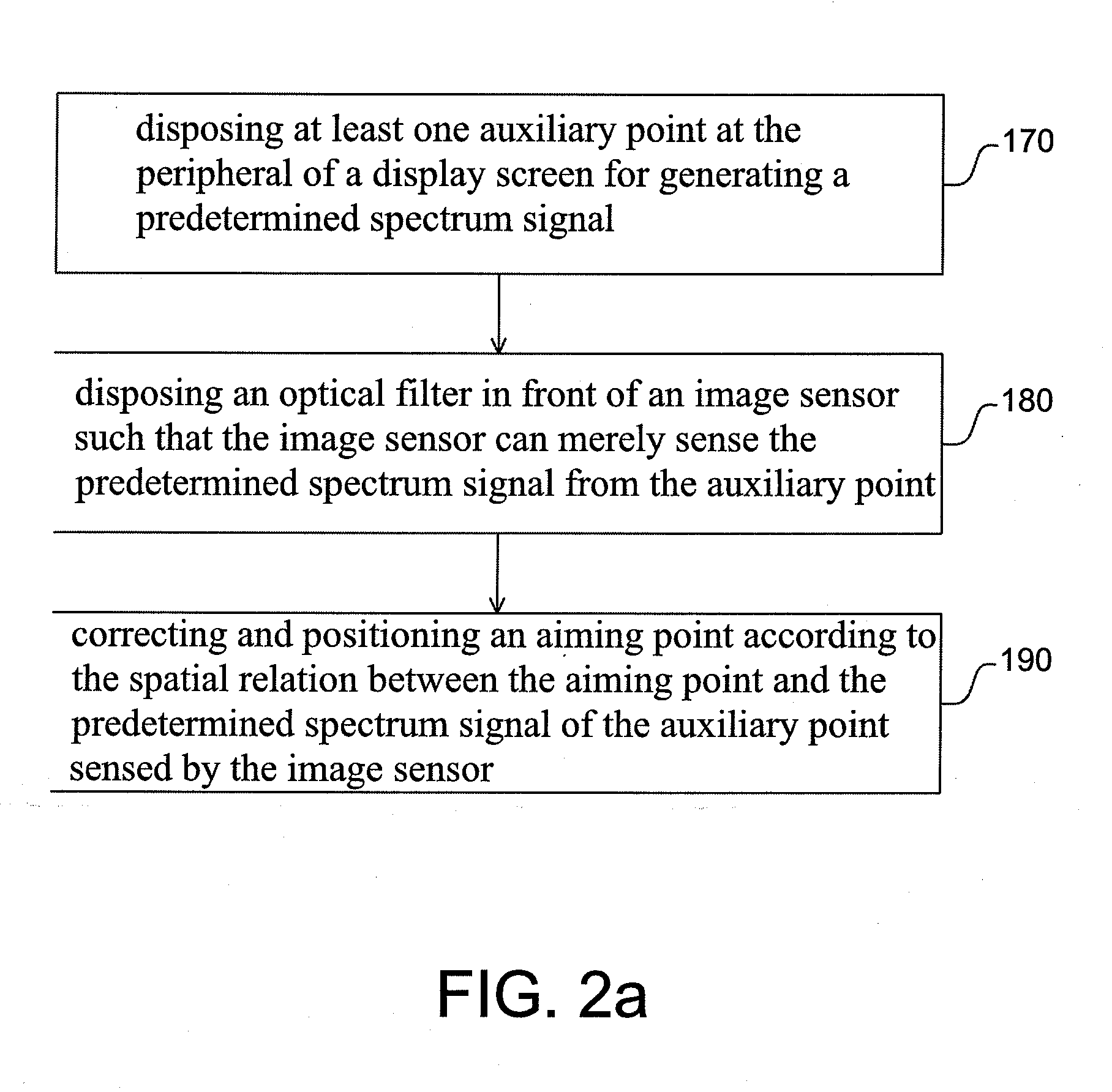
A pointer positioning device for positioning an aiming point on a display screen of an image display comprises at least one auxiliary point, an image sensor and an optical filter. The auxiliary point is disposed at the peripheral of the display screen for generating a predetermined spectrum. The image sensor receives signals of the predetermined spectrum generated by the auxiliary point. The optical filter is disposed in front of the image sensor for filtering out spectrum outside the predetermined spectrum such that the image sensor can merely sense the signals of the predetermined spectrum, wherein the auxiliary point is utilized as a reference point for correcting an initial setup and positioning the aiming point so as to position the aiming point inside a predetermined range on the display screen. The present invention also provides a pointer positioning method adapted to the pointer positioning device.

Description

CROSS REFERENCE TO RELATED APPLICATION[0001]This application claims the priority benefit of Taiwan Patent Application Serial Number 095116011 filed on May 5, 2006, the full disclosure of which is incorporated herein by reference.BACKGROUND OF THE INVENTION[0002]1. Field of the Invention[0003]This invention generally relates to a pointer positioning device and method, which utilizes an image sensor integrated with an optical filter for sensing signals of a predetermined spectrum generated by an auxiliary point for positioning an aiming point of the image sensor on a display screen.[0004]2. Description of the Related Art[0005]A conventional pointer positioning device is disclosed in Taiwan Patent No. 1232769 entitled “A vision feedback system utilized in ray gun”. It is utilized for extracting optical point signals or optical coordinate signals sent from a ray gun to a video game system. A control circuit calculates optical point coordinate signals according to horizontal and vertical...

Claims


Application Information

Patent Timeline
IPC IPC(8): G09G5/08
CPCG09G3/001G09G2320/028G09G5/08
Inventor CHAO, TZU YIWU, MENG TSUNGLIN, CHIH HSINCHEN, HSIN CHIAHUANG, CHAO CHIENLEE, HSUAN HSIENLEE, YI FANG
Owner PIXART IMAGING INC
Learn More