Underground micro-irrigation device

A micro-irrigation and consistent technology, applied in watering devices, horticulture, botany equipment and methods, etc., can solve the problems of easy clogging of the irrigation device and poor water absorption, achieve good water saving effect, and improve crop yield and quality. , the effect of reducing the cost of system construction and use

Inactive Publication Date: 2013-02-06
KUNMING UNIV OF SCI & TECH
View PDF12 Cites 15 Cited by
  • Summary
  • Abstract
  • Description
  • Claims
  • Application Information

AI Technical Summary

Problems solved by technology

[0004] The purpose of the present invention is to provide an underground micro-irrigation device, which can irrigate crops at the best position to meet the water requirements of crops, and the irrigation position and depth can be adjusted to solve the problem of poor water absorption by the root system. easy clogging problem

Method used


Image

  • Underground micro-irrigation device
  • Underground micro-irrigation device
  • Underground micro-irrigation device

Examples


Embodiment 1

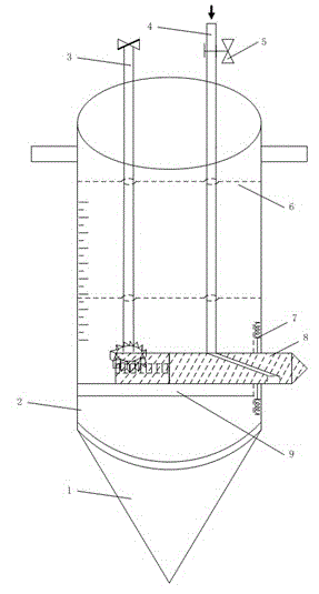
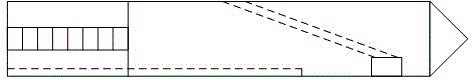
[0022] Embodiment 1: as Figure 1-2 As shown, an underground micro-irrigation device includes a soil-breaking cone 1 and an outer pipe 2. The soil-breaking cone 1 is installed at the lower end of the outer pipe 2. It is characterized in that: the outer pipe 2 is equipped with an advancing and retreating rotating rod 3, an inlet pipe 4, and a fixer. 6. The soil scraper 7, the sprinkler 8, and the fixer 6 are installed in the middle of the outer pipe 2. The forward and backward rotation rod 3 and the water inlet pipe 4 are installed in the outer pipe 2 through the fixer 6. The scraper 7 is installed on the inner and lower side of the outer pipe 2. 2 The lower part is equipped with a slide rail 9, and the sprinkler 8 is installed on the slide rail 9.

[0023] The soil-breaking cone 1 is a solid cone, and the soil-breaking cone 1 is installed in the outer pipe 2 lower ends by the screw thread that its upper end is provided with. Outer tube 2 is a circular tube, and its outer wall...

Embodiment 2

[0026] Embodiment 2: as Figure 1-2 As shown, an underground micro-irrigation device includes a soil-breaking cone 1 and an outer pipe 2. The soil-breaking cone 1 is installed at the lower end of the outer pipe 2. It is characterized in that: the outer pipe 2 is equipped with an advancing and retreating rotating rod 3, an inlet pipe 4, and a fixer. 6. The soil scraper 7, the sprinkler 8, and the fixer 6 are installed in the middle of the outer pipe 2. The forward and backward rotation rod 3 and the water inlet pipe 4 are installed in the outer pipe 2 through the fixer 6. The scraper 7 is installed on the inner and lower side of the outer pipe 2. 2 The lower part is equipped with a slide rail 9, and the sprinkler 8 is installed on the slide rail 9.

[0027] The soil-breaking cone 1 is a hollow cone, and the soil-breaking cone 1 is installed in the outer pipe 2 lower ends by the screw thread that its upper end is provided with. Outer tube 2 is a circular tube, and its outer wal...


PUM


Abstract

The invention relates to an underground micro-irrigation device, and belongs to the technical field of agricultural water-saving irrigation. The underground micro-irrigation device disclosed by the invention comprises a groundbreaking cone and an outer tube, wherein the groundbreaking cone is arranged at the lower end of the outer tube, an advance-retreat rotating rod, a water inlet pipe, a fixator, a soil scraper and an emitter are arranged in the outer tube, the fixator is arranged in the middle of the outer tube, the advance-retreat rotating rod and the water inlet pipe are fixed in the outer tube through the fixator, the soil scraper is arranged on the lower side inside the outer tube, a sliding rail is arranged at the lower part of the outer tube, and the emitter is arranged on the sliding rail. The underground micro-irrigation device disclosed by the invention can satisfy the water demands of crops; due to adoption of underground irrigation, water can be saved, so that the root system of a crop can achieve the best water uptake effect, and the utilization efficiency of water can be improved; the device can be inserted and drawn out randomly as required, and does not need to be pre-buried underground, the position and depth of irrigation can be adjusted, and the emitter has small possibility of being jammed; and the device is convenient to carry, easy to install, good in water-saving effect, and easy to popularize and apply.

Description

technical field [0001] The invention relates to an underground micro-irrigation device, which belongs to the technical field of agricultural water-saving irrigation. Background technique [0002] Water is an important factor for crop growth, but traditional irrigation methods do not take into account crop growth and root development, resulting in extremely inefficient water use. However, water supply is in short supply in many parts of the world, therefore, water-saving irrigation is of great significance. By controlling irrigation, it can not only provide better growth conditions for crops, but also achieve the purpose of saving water. [0003] In the past, extensive ground flood irrigation was generally used for agricultural irrigation, which resulted in serious waste of water resources and extremely low efficiency. In recent years, agricultural water-saving irrigation has developed rapidly. The irrigation equipment used in water-saving irrigation includes: sprinkler ir...

Claims


Application Information

Patent Timeline
Patent Type & Authority Applications(China)
IPC IPC(8): A01G25/06
Inventor 杨启良齐亚峰段晓凡
Owner KUNMING UNIV OF SCI & TECH
Why Eureka
Try Eureka