
Polishing head for chemical polishing device and chemical polishing device with polishing head

A technology of chemical grinding device and grinding head, which is applied in the direction of grinding device, grinding machine tool, grinding tool, etc. It can solve the problem that the asymmetric difference of the inner film thickness of the wafer cannot be eliminated by CMP, so as to facilitate the promotion and improve the uniformity of grinding , the effect of simple operation

Inactive Publication Date: 2013-02-06
SHANGHAI HUALI MICROELECTRONICS CORP
View PDF7 Cites 7 Cited by
  • Summary
  • Abstract
  • Description
  • Claims
  • Application Information

AI Technical Summary

Problems solved by technology

[0007] The present invention is aimed at the prior art, the grinding rate of the traditional grinding head used in the chemical grinding device is approximately equal in the area of ​​the same radius from the center of the circle, which leads to defects such as the asymmetric difference in the inner film thickness of the wafer that cannot be eliminated by CMP. A grinding head for a chemical grinding device is provided
[0008] Another object of the present invention is to aim at the polishing rate of the polishing head used in the chemical polishing device in the prior art in the area of ​​the same radius from the center of the circle is approximately equal, which leads to the fact that the asymmetric difference in film thickness inside the wafer cannot be eliminated by CMP, etc. Defectively provide a kind of chemical grinding device with said grinding head

Method used


Image

  • Polishing head for chemical polishing device and chemical polishing device with polishing head
  • Polishing head for chemical polishing device and chemical polishing device with polishing head
  • Polishing head for chemical polishing device and chemical polishing device with polishing head

Examples


Embodiment Construction

[0025] In order to illustrate the technical content, structural features, achieved goals and effects of the present invention in detail, the following will be described in detail in conjunction with the embodiments and accompanying drawings.

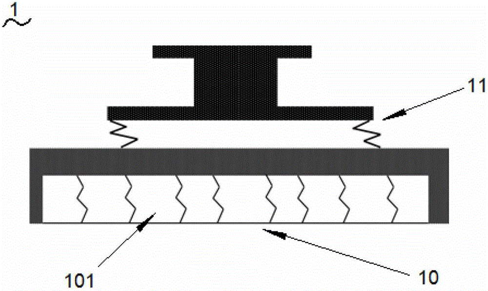
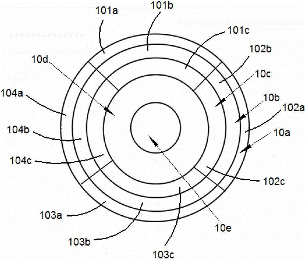
[0026] see figure 1 , figure 2 , figure 1 Shown is a side view of a polishing head for a chemical polishing apparatus according to the present invention. figure 2 Shown is a top view of the polishing head used in the chemical polishing device of the present invention. The grinding head 1 includes a concentric annular grinding area 10 with an independent grinding sub-area 101. The concentric annular grinding area 10 is centered on the center of the grinding head 1 and distributed symmetrically. The independent grinding sub-area 101; the force applying device 11, the force applying device 11 acts on the grinding head 1, and independently controls the force of each grinding sub-area 101. Wherein, the said force applying device 11 in...


PUM


Abstract

A polishing head for a chemical polishing device comprises concentric annular polishing areas with independent polishing subareas, and a force application device, wherein the concentric annular polishing areas are symmetrically distributed by taking the center of the polishing head as the center; the independent polishing subareas are arranged in the concentric annular polishing areas respectively; and the force application device acts on the polishing head and independently controls stresses of the polishing subareas respectively. The invention further relates to the chemical polishing device with the polishing head. The chemical polishing device further comprises a rotating shaft, a polishing table and a polishing pad. Asymmetric polishing in a wafer can be achieved by adopting the polishing head, applying larger pressure in an area with a thicker film and applying smaller pressure in an area with a thinner film, so as to improve the polishing uniformity of asymmetric distribution of film thickness in the wafer. The polishing head is simple to operate, convenient to use and popularize and high in practicability, and can satisfy polishing requirements of different products.

Description

technical field [0001] The invention relates to the technical field of semiconductor devices, in particular to a grinding head for a chemical grinding device and a chemical grinding device thereof. Background technique [0002] Chemical Mechanical Polishing (CMP) is a process that works together through a chemical reaction process and a mechanical polishing process. Generally, during the chemical polishing process, the first polishing head exerts a certain pressure on the back of the first wafer to make the front of the first wafer close to the first polishing pad. At the same time, the first grinding head drives the first wafer and the first grinding pad to rotate in the same direction, so that the front surface of the first wafer and the first grinding pad generate mechanical friction. During the grinding process, a film on the surface of the wafer is removed through a series of complicated mechanical and chemical actions, so as to achieve the purpose of flattening the fi...

Claims


Application Information

Patent Timeline
Patent Type & Authority Applications(China)
IPC IPC(8): B24B37/20B24B37/07
Inventor 邓镭
Owner SHANGHAI HUALI MICROELECTRONICS CORP
Learn More