Rotor aircraft

A rotorcraft and rotorcraft technology, applied in the field of rotorcraft, can solve the problems of affecting the flight stability of the aircraft, affecting the shooting effect, and cannot completely eliminate the torque difference, etc., and achieve the effect of simple structure, convenient setting and ensuring stability

Inactive Publication Date: 2013-02-06
深圳市联讯创新工场科技开发有限公司
View PDF4 Cites 9 Cited by
  • Summary
  • Abstract
  • Description
  • Claims
  • Application Information

AI Technical Summary

Problems solved by technology

The multi-rotor aircraft balances the aircraft through the torque generated by each rotor that can cancel each other out, but the aircraft cannot completely eliminate the influence of the torque difference, causing the aircraft to rotate or shake left and right, thereby affecting the flight stability of the aircraft, especially for aerial photography. The aircraft will affect the effect of its shooting

Method used


Image

  • Rotor aircraft
  • Rotor aircraft
  • Rotor aircraft

Examples


Embodiment 1

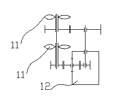
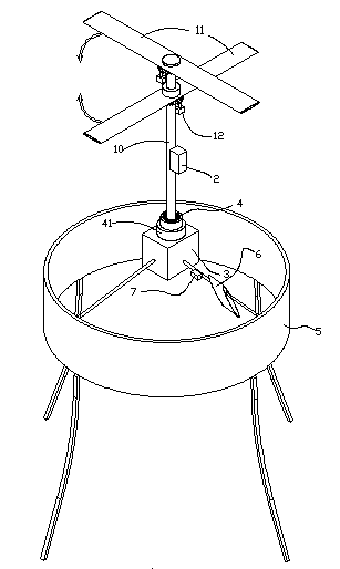
[0037] figure 1 Shown is a kind of rotorcraft of the present invention, comprises rotor 11, rotor power driving part, control part 2 and load part 3 that control described rotorcraft takeoff and landing and turning, between described rotor power driving part and load part 3 A torque isolation part 4 is provided; wherein, the torque isolation part 4 is an isolation bearing 40, and the load part 3 is provided with a strut 10, and the inner ring of the isolation bearing 40 is fixedly connected with the strut 10, and the The outer ring of the isolation bearing 40 is fixedly connected to the load part 3, and the rotor power drive part drives the rotor 11 to rotate relative to the pole 10; the control part 2 is a radio device, and the control part 2 is provided with a transmitting and receiving command device To control the start and stop of the rotor power drive part; the rotor power drive part includes a power source 13 and a drive motor 12, and the rotor 11 shares a drive motor 1...

Embodiment 2

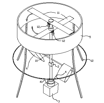
[0044] Figure 4 Shown is a kind of rotorcraft according to the present invention, comprising rotor 11, rotor power drive part, control part 2 and load part 3 for controlling the landing and steering of the rotorcraft, the rotor power drive part and load part 3 There is also a torque isolation part 4 between them; the control part 2 is arranged between the rotor 11 and the load part 3, and the torque isolation part 4 is arranged between the control part 2 and the load part 3 . Wherein, the torque isolation part 4 is an isolation bearing 40, the load part 3 is provided with a strut 10, the outer ring of the isolation bearing 40 is fixedly connected with the strut 10, and the inner ring of the isolation bearing 40 is connected to the The load part 3 is fixedly connected. The power drive part of the rotor is an internal combustion engine; the number of the rudders is replaced by three, one of which is set on the side of the load, and the other two are horizontally symmetrically...


PUM


Abstract

The invention relates to a rotor aircraft comprising rotors, a rotor power driving portion, a controlling portion used for controlling taking-off, landing, and steering of the rotor aircraft, and a load portion. The rotor aircraft is characterized in that a torque isolation portion is arranged between the rotors and the load portion. In prior arts, because of the torque differences of rotors on the aircraft, great influence is applied on the rotor aircraft, aircraft flight stability is influenced, and especially parts such as loads arranged on the aircraft would rotate or sway left and right. With the rotor aircraft provided by the invention, the problem is solved. Parts such as loads do not rotate with the rotation of the rotors, such that the parts such as the loads can operates stably. The rotor aircraft is especially suitable to be used in aerial photography or aerial reconnaissance.

Description

technical field [0001] The invention relates to a flying device, in particular to a rotorcraft. Background technique [0002] The single-rotor aircraft balances the torque produced by the rotor by adding a tail rotor at the tail of the aircraft. The dual-rotor aircraft is balanced by the torque produced by the two rotors that can cancel each other to eliminate the impact of the rotation of the rotors on the aircraft. The multi-rotor aircraft balances the aircraft through the torque generated by each rotor that can cancel each other out, but the aircraft cannot completely eliminate the influence of the torque difference, causing the aircraft to rotate or shake left and right, thereby affecting the flight stability of the aircraft, especially for aerial photography. The aircraft will affect the effect of its shooting. Contents of the invention [0003] For this reason, the technical problem to be solved by the present invention is that the rotorcraft described in the prior...

Claims


Application Information

Patent Timeline
Patent Type & Authority Applications(China)
IPC IPC(8): B64C27/10B64D27/24
Inventor 孙海翔李庆松朱亮窦新国钟强
Owner 深圳市联讯创新工场科技开发有限公司
Why Eureka
Try Eureka