Automatic puncture feeding device

A feeding device and automatic technology, applied in the direction of conveyor objects, transportation and packaging, furnaces, etc., can solve the problem of putting the cloth on the special piercing frame by manual operation, and then knocking the cloth into the piercing frame with a self-made hollow hammer Then manually push the puncture frame into the oven, bake it for about 60 seconds in an environment of 200°C to 250°C, and then pull the puncture frame out of the oven and push it to the top of the mold on the hydraulic press to reduce the heat loss of the oven. and low efficiency, high labor intensity of workers, etc., to achieve the effect of simple and convenient operation, automatic control, and shortened production cycle

Active Publication Date: 2013-02-06
CHONGQING HONGNAN MACHINERY
View PDF6 Cites 7 Cited by
  • Summary
  • Abstract
  • Description
  • Claims
  • Application Information

AI Technical Summary

Problems solved by technology

Although some enterprises use manipulators for automatic operation in the process of edge material cutting, most enterprises still use traditional and backward production processes for the first few processes, that is, manually put the cloth into a special piercing machine. Then use a self-made hollow hammer to knock the fabric into the nails on the puncture frame, then manually push the puncture frame into the oven, bake it in an environment of 200°C to 250°C for about 60 seconds, and then manually put the puncture frame into the oven. Pull it out from the oven and push it to the top of the mold on the hydraulic press. After starting the hydraulic press, the upper and lower molds are closed, and the finished product is produced after pressing for about 60 seconds. The entire production process takes about 180-200 seconds, and the output per shift

Method used


Image

  • Automatic puncture feeding device
  • Automatic puncture feeding device
  • Automatic puncture feeding device

Examples


Embodiment Construction

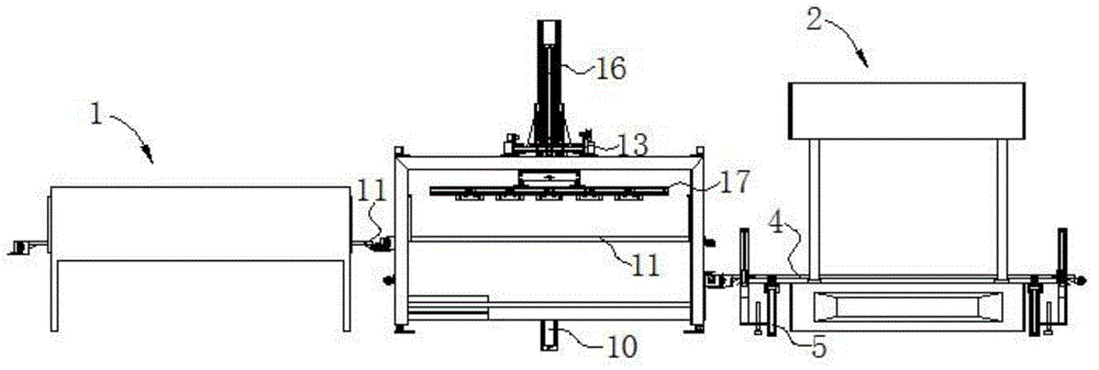
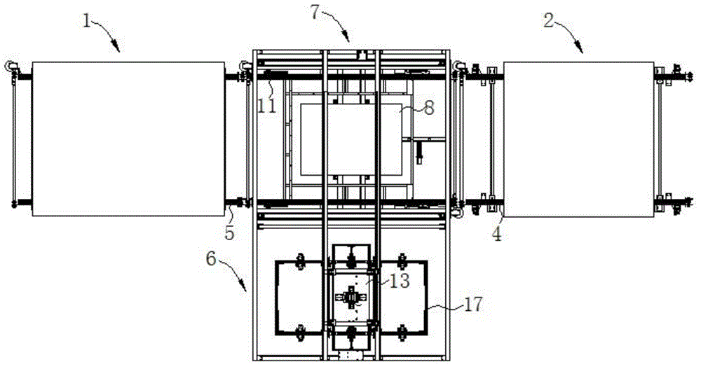
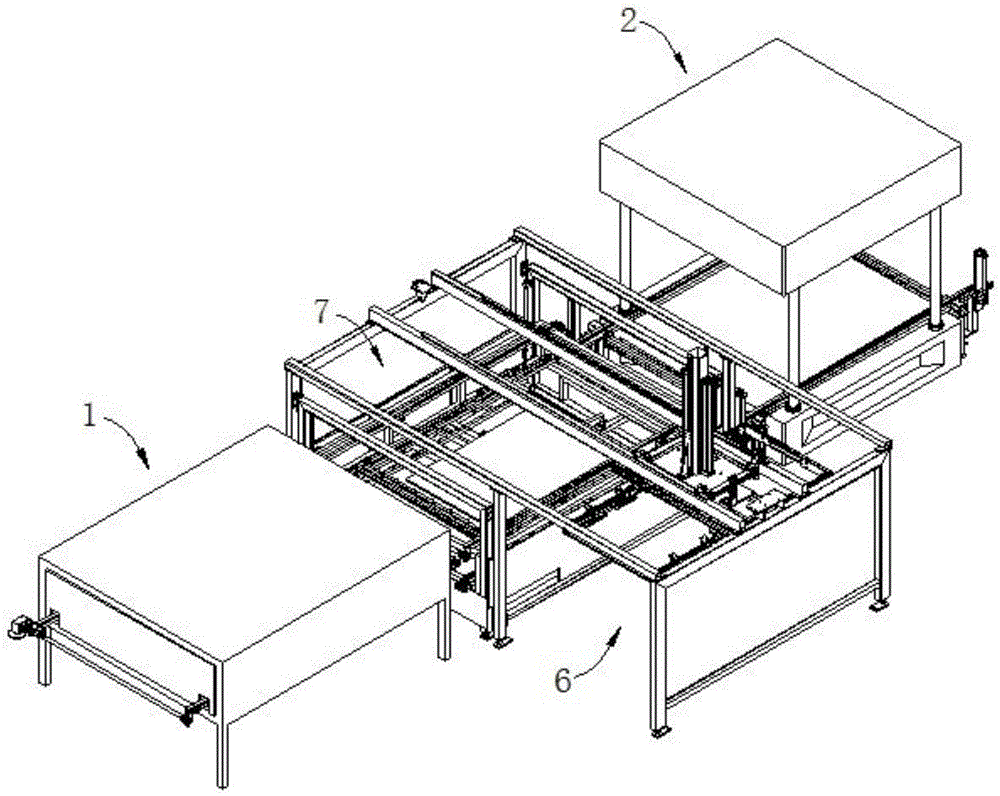
[0032] The present invention will be further described below in conjunction with accompanying drawing:

[0033] like figure 1 , 2 , shown in 3, a kind of automatic puncture feeding device, comprises oven 1, hydraulic press 2; Baking track 3 is set in oven 1; On the press track cylinder 5; also include automatic grabbing device 6 and double-layer frame lifting device 7; The layer frame 9 is installed on the base 8, the upper layer track 11 and the lower layer track 12 are arranged in the double layer frame 9, and the puncture frame 38 is placed on the lower layer track 11; .

[0034] like Figure 5 , 6As shown, the two ends of the base 8 are provided with gantry-type columns 23 respectively, and the optical axis guide rail 24 is installed on the column 23, and the box-type linear sliding slider 25 is arranged on the optical axis guide rail 24, and the box-type linear sliding slider 25 passes through the fixed plate 26 and Double-layer frame 9 is fixedly connected.

[003...


PUM


Abstract

The invention discloses an automatic puncture feeding device which comprises a baking oven and a hydraulic machine. A baking rail is arranged in the baking oven; a press lifting rail is arranged in the hydraulic machine; the automatic puncture feeding device also comprises an automatic grasping device and a double-layer frame lifting device; the double-layer frame lifting device comprises a base and a double-layer frame; an upper layer rail and a lower layer rail are arranged in the double-layer frame; a movable open-close type puncture frame is laid on the lower layer rail; and the upper layer tail and the lower layer rail of the double-layer frame are positioned between the baking rail and the press lifting rail. The automatic puncture feeding device realizes the automated production of loading, puncture, baking and pressing processes, after the automatic puncture feeding device is adopted, the movable open-close type puncture frame can realize that the hydraulic machine can automatically withdraw the puncture frame from a die in advance before die assembly, and by adopting the operating mode of double-frame circulating lifting rails, the production time is greatly shortened, and the production efficiency is effectively improved.

Description

technical field [0001] The invention relates to a production and processing device for automotive interior parts, in particular to a device capable of synchronously completing automatic puncture feeding, baking and pressing of the interior parts. Background technique [0002] At present, domestic automotive interior parts production enterprises generally have a production process as follows: loading → threading → baking → pressing → edge cutting → finished product. Although some enterprises have adopted manipulators for automatic operation in the process of edge material cutting, most enterprises still use relatively traditional and backward production processes for the first few processes, that is, manually put the cloth into a special piercing machine. On the frame, use a self-made hollow hammer to knock the cloth into the nails on the puncture frame, then manually push the puncture frame into the oven, bake it in an environment of 200℃~250℃ for about 60 seconds, and then ...

Claims


Application Information

Patent Timeline
IPC IPC(8): B65G49/00
Inventor 刘才平刘朝民刘芷彤
Owner CHONGQING HONGNAN MACHINERY
Why Eureka
Try Eureka