
Winder and method for winding wire on winder

一种缠绕电线、绕线器的技术,应用在线圈、电路、线圈制造等方向,能够解决绕线方法费力、耗时、无法精确地控制末端产品品质等问题,达到减少工作时间、简化步骤的效果

Active Publication Date: 2013-02-06
DELTA ELECTRONICS (SHANGHAI) CO LTD +1
View PDF5 Cites 6 Cited by
  • Summary
  • Abstract
  • Description
  • Claims
  • Application Information

AI Technical Summary

Problems solved by technology

[0004] The above-mentioned winding method is quite laborious and time-consuming, and is not economical
In addition, through the manual winding production method, the winding quality is unstable, and the quality of the end product cannot be accurately controlled

Method used


Image

  • Winder and method for winding wire on winder
  • Winder and method for winding wire on winder
  • Winder and method for winding wire on winder

Examples


Embodiment Construction

[0061] The preferred embodiments of the present invention are described hereby in conjunction with the accompanying drawings.

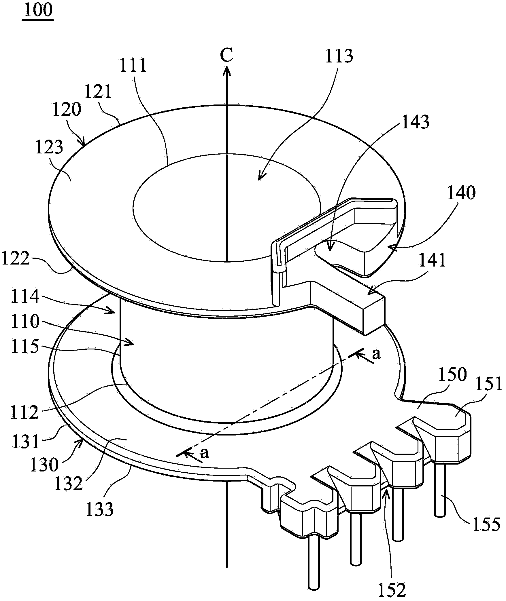
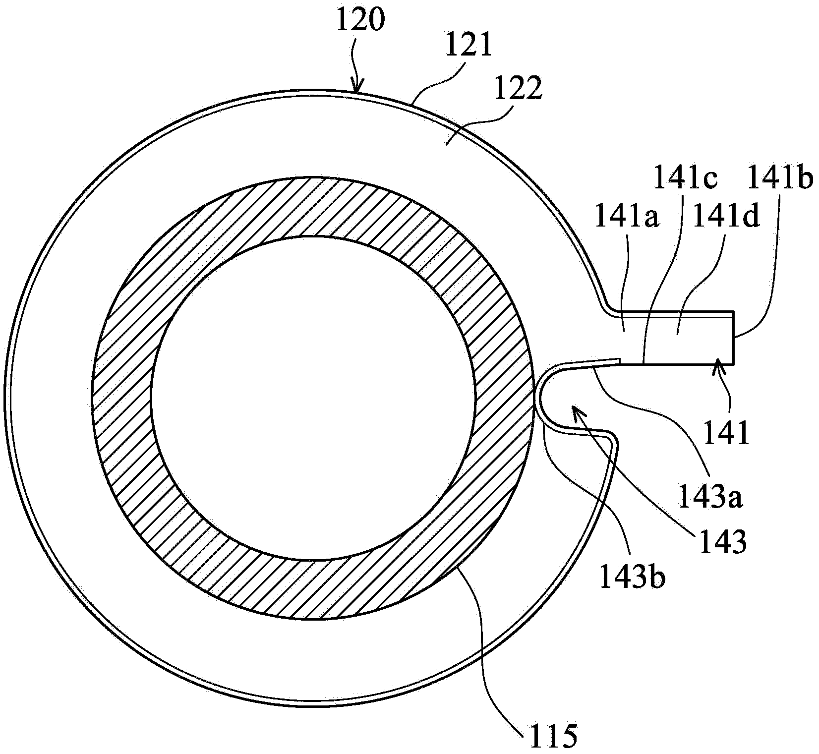
[0062] Please refer to Figures 2A and 2B, where Figure 2B show Figure 2A The cross-sectional view viewed from the a-a section line towards the axis C. The cable winder 100 according to the first embodiment of the present invention includes a body 110 , a first baffle 120 , a second baffle 130 , a guide 140 , an extension 150 and a plurality of conductive pins 155 .

[0063] The body 110 is a hollow cylinder with two ends 111 , 112 and a channel 113 . The body 110 extends on an axis C, and two end portions 111 , 112 are defined on two sides of the body 110 on the axis C, respectively.

[0064] The first baffle 120 circumferentially surrounds the end portion 111 of the body 110 and extends radially. The second baffle 130 circumferentially surrounds the end portion 112 of the body 110 and extends radially. The peripheral edges 121 and 131 of the f...


PUM


Abstract

The invention provides a winder and a method for winding a wire on the winder. The winder comprises a body, a first baffle, a second baffle and at least one guide part. The body extends on an axis; and the first baffle and the second baffle circumferentially surround the end parts of the body and extend in the radial direction. The guide part is formed on the first baffle or the second baffle and comprises at least one fake pin radially protruding from the first baffle or the second baffle, wherein the fake pin is made of an insulator material. Through the structural relation between the guide part in the winder and a winding region, a step of utilizing an adhesive tape to fix the wire on the winder in the prior art can be saved. Therefore, not only are the steps required by the winding operation simplified, but also the working time required by the manual operation is reduced.

Description

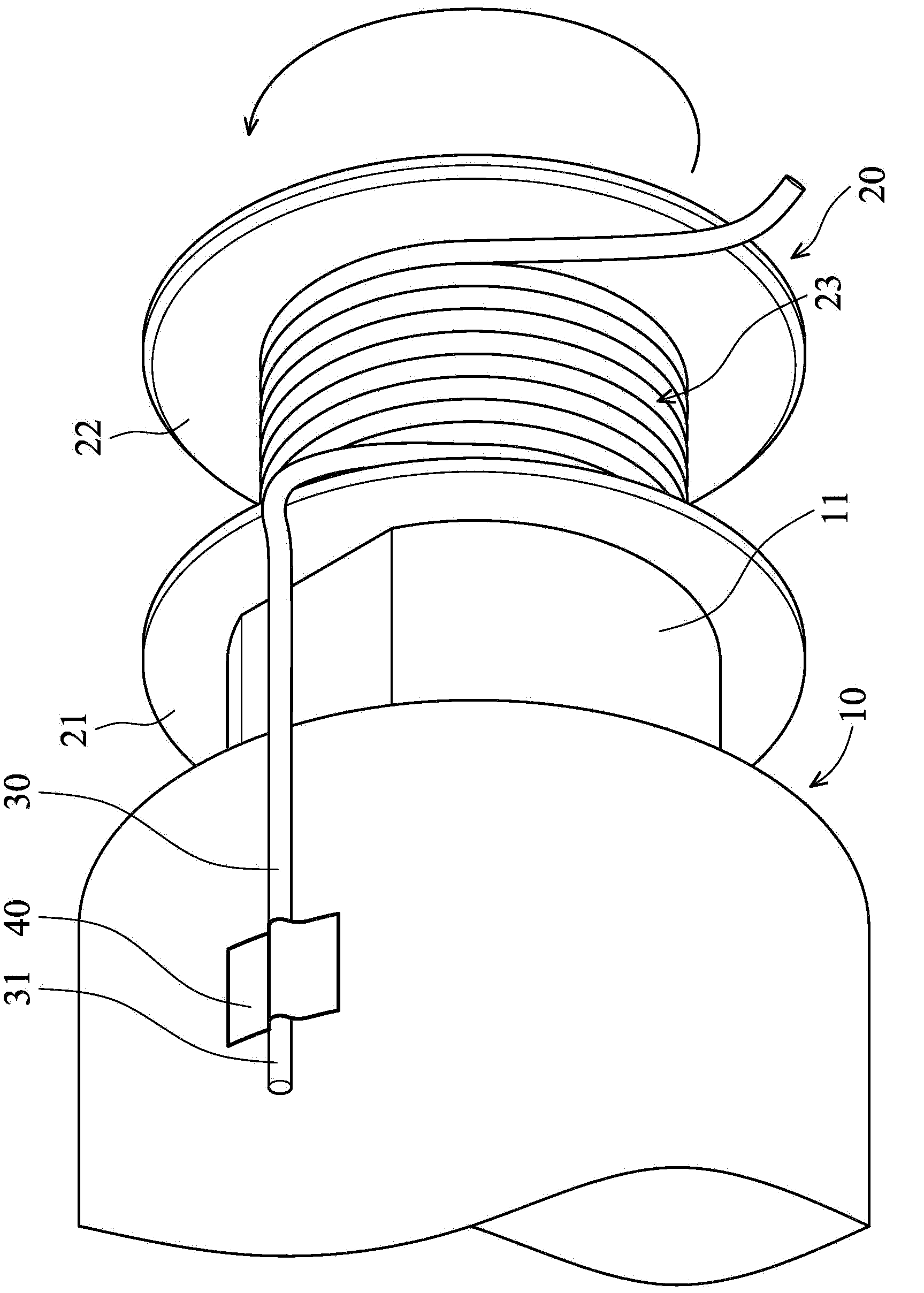
technical field [0001] The invention relates to a wire winder and a method for winding electric wires on the wire winder, in particular to a wire winder with guides for fixing electric wires thereon and a method for winding electric wires on the wire winder. Background technique [0002] It is well known in the art to wind electric wires on a bobbin having a hollow cylindrical structure. See figure 1 , the existing winding machine 10 has a winding shaft 11 passing through the structural center of the winding device 20 to drive it to rotate. Both ends of the wire winder 20 have two baffles 21, 22 defining a wire winding area 23 therein. [0003] When winding the electric wire 30 , firstly, a tape 40 is used to manually fix the first end 31 of the electric wire 30 on the winding machine 10 . Next, the wire winder 20 is rotated to wind the wire 30 in the wire winding area 23 . [0004] The above-mentioned winding method is quite laborious and time-consuming, and is not econ...

Claims


Application Information

Patent Timeline
Patent Type & Authority Applications(China)
IPC IPC(8): B65H54/10B65H54/70
CPCB65H54/10B65H54/70H01F41/0687B65H75/28H01F5/04H01F41/10
Inventor 陈诗云颜錞靖顾彩利林财申
Owner DELTA ELECTRONICS (SHANGHAI) CO LTD
Learn More