Low friction sheave bracket

A pulley bracket and frame technology, applied in transportation and packaging, railway car body parts, mining cars, etc., can solve the problems of reducing the life of dragging cables, increasing tension and resistance, etc.

Inactive Publication Date: 2013-02-06
JOY GLOBAL UNDERGROUND MINING LLC
View PDF9 Cites 3 Cited by
  • Summary
  • Abstract
  • Description
  • Claims
  • Application Information

AI Technical Summary

Problems solved by technology

Additionally, the contacting metal plate pulling the cable creates friction, increasing tension and resistance
The combination of friction-induced heat and strain on snagged cables (e.g. splices) greatly reduces trailing cable life

Method used


Image

  • Low friction sheave bracket
  • Low friction sheave bracket
  • Low friction sheave bracket

Examples


Embodiment Construction

[0016] Before any individual embodiment of the invention is explained in detail, it is to be understood that the invention is not limited in its application to the details of construction and arrangement of parts set forth in the following description or shown in the following drawings. The invention is capable of other embodiments and of being practiced or carried out in various ways. Also, it is to be understood that the phraseology and terminology used herein are for the purpose of description and should not be regarded as limiting. The use of "comprises," "including," or "having" and variations thereof herein is meant to encompass the items listed thereafter and equivalents thereof as well as additional items. Unless otherwise specified or limited, the terms "mount," "connect," "support," and "coupling" and variations thereof are used broadly and encompass direct and indirect mounting, connections, supports, and couplings. Furthermore, the terms "connected" and "coupled" ...


PUM


Abstract

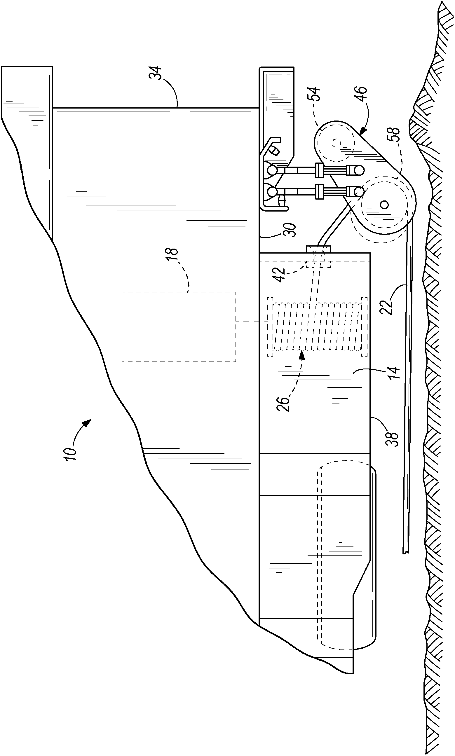
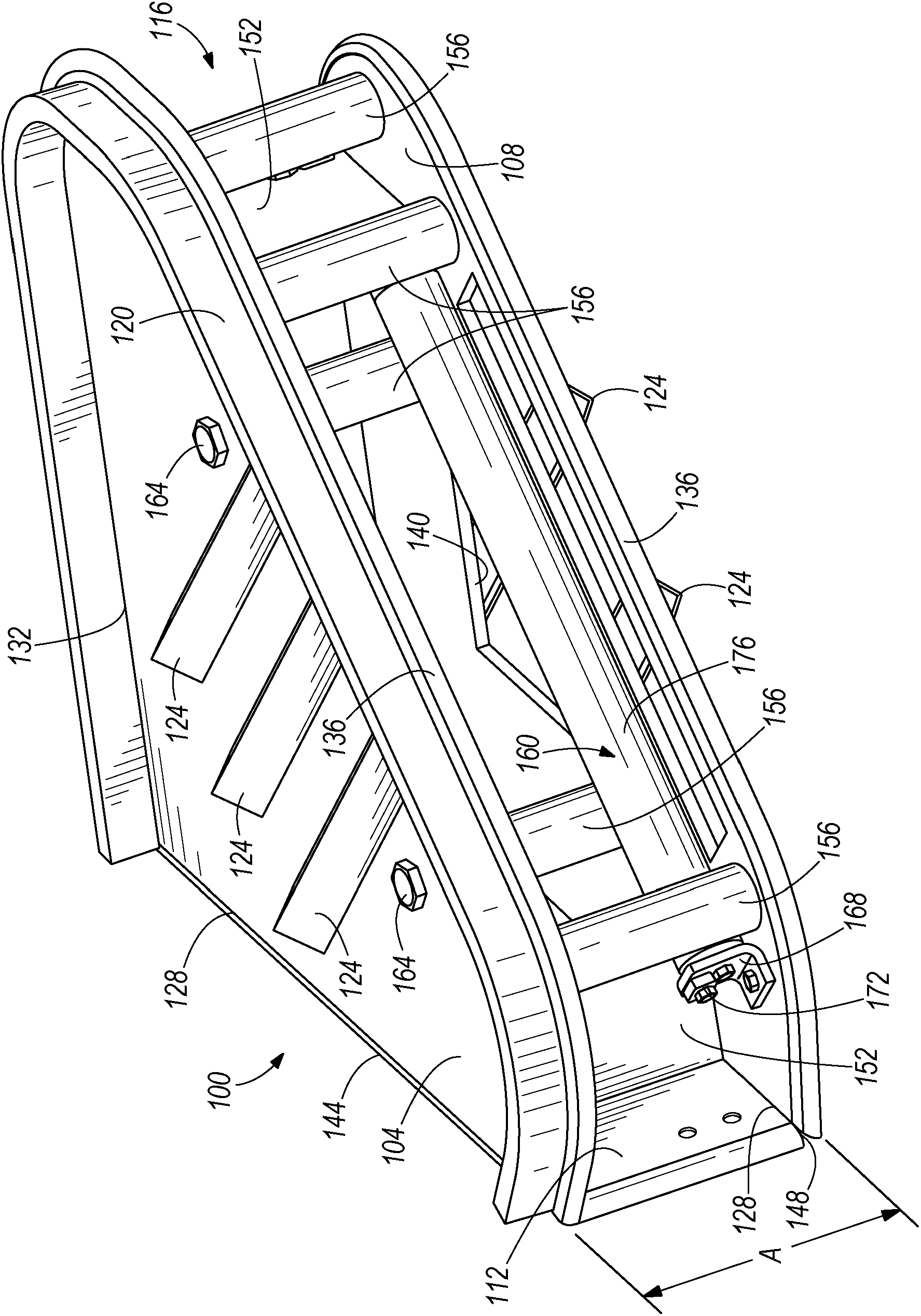
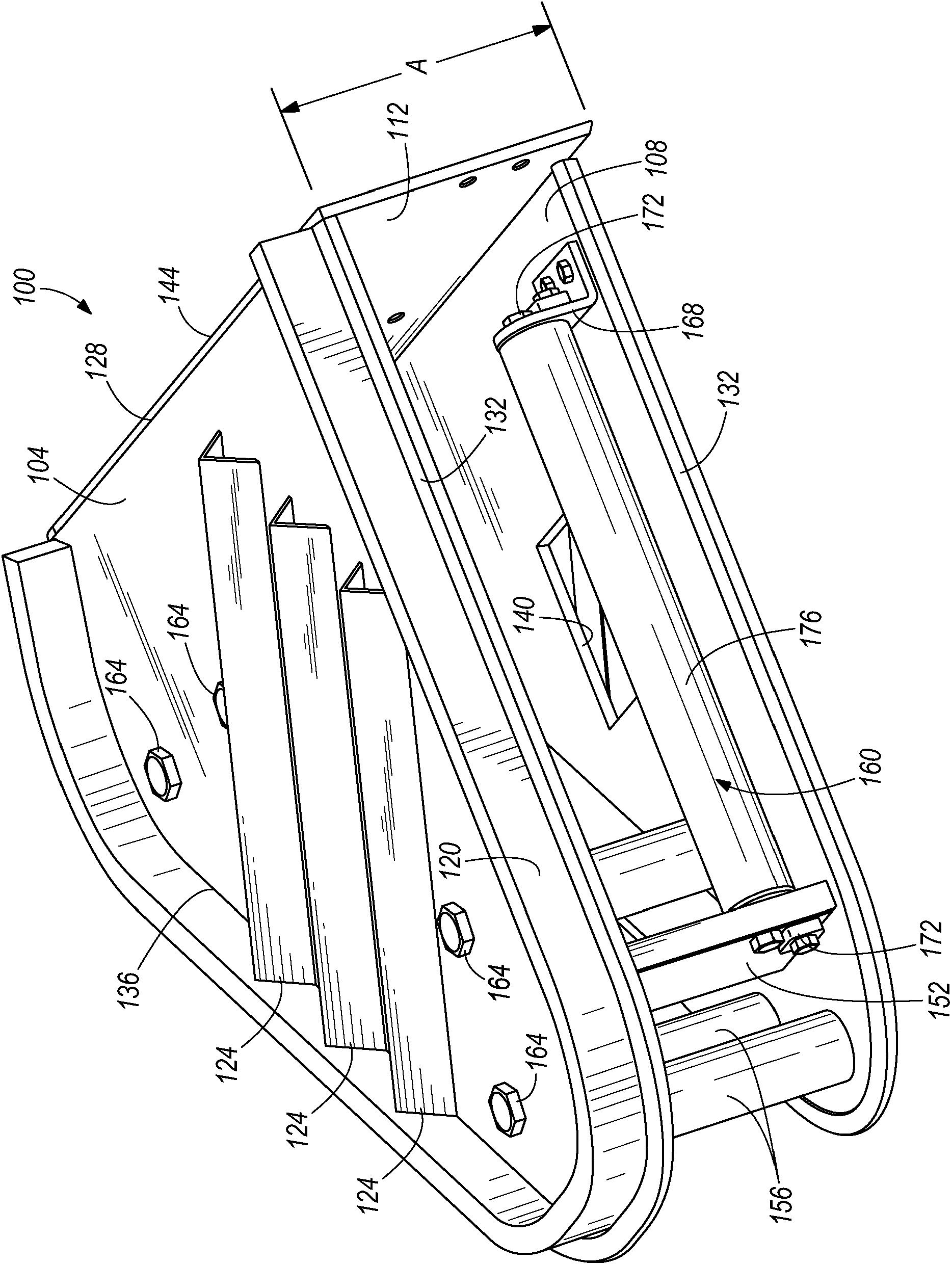
The invention relates to a low friction sheave bracket. An electrically powered mining vehicle including a frame rollingly supported on a surface for movement over the surface. An electric motor is coupled to the frame for proving power to the vehicle. A cable is electrically coupled to the electric motor for supplying electricity thereto and a cable management system is coupled to the frame and arranged to receive and payout the cable as the vehicle moves over the surface. A sheave bracket is coupled to the frame and arranged to direct the cable into the cable management system and includes a lower plate arranged substantially horizontally, a plurality of vertical rollers that are coupled to the lower plate and are arranged to guide the cable into the cable management system, and a horizontal roller that is coupled to the lower plate and arranged to elevate the cable above the lower plate.

Description

[0001] related application [0002] This application claims the benefit of US Provisional Patent Application No. 61 / 513,858, filed August 1, 2011, which is hereby incorporated by reference in its entirety. technical field [0003] The present invention relates to mining shuttle cars, and more particularly, the present invention relates to pulley brackets for mining shuttle cars. Background technique [0004] Mobile electric machines, such as shuttle cars used to carry mining material in underground mines, have electric motors connected by cables to a power source. As the machine moves backwards, forwards, and around corners, the cable is wound onto and paid out from the reel. The cable extends from the rear side of the shuttle car and, sometimes, runs along the side of the shuttle car when the shuttle car is moving rearward, or runs straight back from the shuttle car when the shuttle car is moving forward. As the shuttle car moves around corners, the cable runs along the r...

Claims


Application Information

Patent Timeline
Patent Type & Authority Applications(China)
IPC IPC(8): B65H57/14B61D11/00
CPCB60L2200/36B60L9/00B65H57/14B65H2701/34B61D11/00B60L2200/40
Inventor 斯蒂芬·费利克斯道格拉斯·安德森威廉·朱贝克
Owner JOY GLOBAL UNDERGROUND MINING LLC
Why Eureka
Try Eureka