
Device for measuring material surface by using blast furnace based on multiple input multiple output (MIMO) radar

A technology of radar and material surface, applied in the direction of inspection devices, etc., can solve the problems of multiple laser rangefinders, high cost, and large difference in material surface shape, and achieve high anti-interference ability, high reliability, and high resolution Effect

Inactive Publication Date: 2013-02-06
BEIHANG UNIV
View PDF13 Cites 17 Cited by
  • Summary
  • Abstract
  • Description
  • Claims
  • Application Information

AI Technical Summary

Problems solved by technology

Since the data is not obtained by directly measuring the information of the material level, the error of the material level obtained by processing the data will increase. Another disadvantage is that a large amount of data must be required to obtain ideal information. Due to the concentration of the laser The performance is very good, but a lot of laser equipment is needed to measure the pattern
[0013] In the Chinese Patent Publication No. CN102312031A, the invention patent "Measuring Device and Method for Blast Furnace Roof Material Level Without Material Bell", it uses the existing mechanical probe in the blast furnace to install a laser rangefinder, gyroscope and wireless transmission on it. The device constitutes a material level measurement system. The existing problem is that the blast furnace system it measures is a bellless blast furnace, which has great limitations on the application premise; There are many instruments and the cost is high; finally, the measured data are only points on a line on the material surface (the number of measured real data is related to the number of lasers), and the number of installed laser rangefinders is limited. This will lead to the incompleteness of the collected data, so that a large amount of data on the material surface is obtained by fitting, and the final shape of the material surface may be quite different from the real material surface

Method used


Image

  • Device for measuring material surface by using blast furnace based on multiple input multiple output (MIMO) radar
  • Device for measuring material surface by using blast furnace based on multiple input multiple output (MIMO) radar
  • Device for measuring material surface by using blast furnace based on multiple input multiple output (MIMO) radar

Examples


Embodiment Construction

[0040] Examples of the present invention will be described below in conjunction with the accompanying drawings.

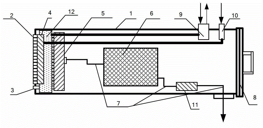
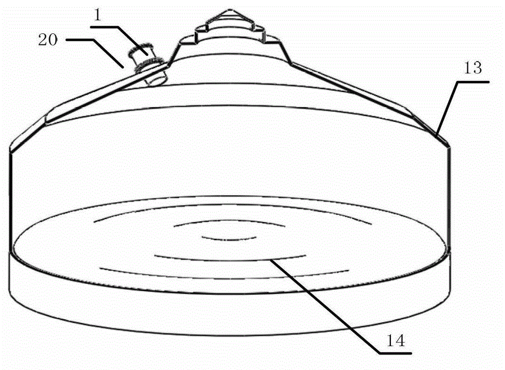
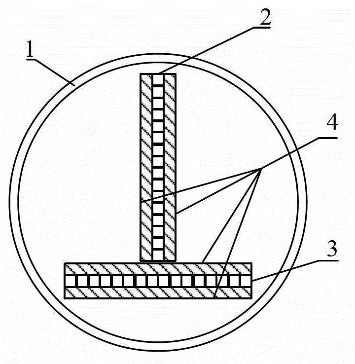
[0041] figure 1 It is a schematic cross-sectional side view of the device of the present invention, wherein the radar protection sleeve 1 of the device of the present invention plays an integral role in protecting the MIMO radar, preventing high temperature and dust and rain impact. In the embodiment of the present invention, the radar sleeve is made of stainless steel. The front end of the barrel is covered with high temperature resistant ramming material to insulate the high temperature in the furnace and protect the sleeve. The main body of the MIMO radar includes a transmitting antenna array 2 and a receiving antenna array 3. The transmitting antenna array 2 and the receiving antenna array 3 form a MIMO array through a T-shaped array or a cross-shaped array. In the embodiment of the present invention, the antenna unit adopts a special high-temperature resistant...


PUM


Abstract

The invention relates to a device for measuring a material surface by using a blast furnace based on an MIMO radar. The device is a set of system composed of an MIMO radar, antenna arrays, an antenna protection casing, a cooling blowing unit and the like. Three-dimensional information of a whole bacterial surface in the blast furnace is obtained by using sparse array high resolution characteristics of the MIMO radar and a near field high resolution imaging algorithm, costs of electronic control scanning array imaging radars are decreased greatly simultaneously, and on-line dynamic monitoring capacity of three-dimensional material surfaces under bad conditions of industrial sites is provided by a dust and high temperature resistance technology.

Description

technical field [0001] The invention relates to a device for measuring the material level of a blast furnace radar based on MIMO, which is used for the on-line dynamic monitoring capability of the three-dimensional material level under harsh conditions in industrial sites. Background technique [0002] The monitoring of the material level in the blast furnace is very important in steel production. On the one hand, through the observation of the material level, the distribution of the furnace material in the blast furnace can be known, so that the production personnel can carry out targeted control on the next distribution according to the distribution of the material level. To improve production efficiency; on the other hand, when the distribution of the material surface in the blast furnace is abnormal, the on-site operators can immediately take corresponding measures to ensure the smooth progress of production and avoid safety accidents. [0003] At present, the commonly u...

Claims


Application Information

Patent Timeline
Patent Type & Authority Applications(China)
IPC IPC(8): C21B7/24
Inventor 许鼎李志平武建华王正鹏
Owner BEIHANG UNIV
Learn More