Construction method of precipitation well

A construction method and technology for dewatering wells, which are applied in infrastructure engineering, construction, sheet pile walls, etc., can solve the problems of high environmental protection pressure, scrapped wells, and difficult to flush, so as to reduce labor costs, reduce auxiliary workers, and prevent sludge. influx effect

Active Publication Date: 2013-02-06
CCCC THIRD HARBOR ENG +1
View PDF4 Cites 11 Cited by
  • Summary
  • Abstract
  • Description
  • Claims
  • Application Information

AI Technical Summary

Problems solved by technology

[0002] The key to well completion in the existing technology lies in the reasonable selection of the specific gravity of the mud when the hole is formed. If the specific gravity of the prepared mud is too large, the viscosity will also increase, the mud skin on the well wall will thicken, and the open hole drilling time will be maintained longer, so that there is enough time Casing, but it is difficult to dilute the mud, and it takes a long time to wash the well, and it is even difficult to flush and the wellbore is scrapped, so it takes time to prepare repeatedly according to the site conditions
Furthermore, the work efficiency is low (it takes 3-4 hours to form a hole, if the power of the drilling rig is low or the workers are not skilled in operation, the time will be longer; it takes about 2 hours to clean the hole) and a large amount of waste is generated due to the need for mud wall protection when forming the hole Slurry does not meet the requirements of environmental protection, and it needs to increase the cost for non-polluting treatment of mud
[0003] Because the East Artificial Island of the Hong Kong-Zhuhai-Macao Bridge is located in the Chinese White Dolphin Reserve, the construction process has high environmental protection requirements, and 82 precipitation wells need to be drilled in the East Artificial Island. If the traditional hole-forming process continues to be used, a large amount of waste will be generated. Mud, environmental protection pressure

Method used


Image

  • Construction method of precipitation well
  • Construction method of precipitation well
  • Construction method of precipitation well

Examples


Embodiment Construction

[0031] In order to make the technical means, creative features, goals and effects achieved by the present invention easy to understand, the present invention will be further described below in conjunction with specific illustrations.

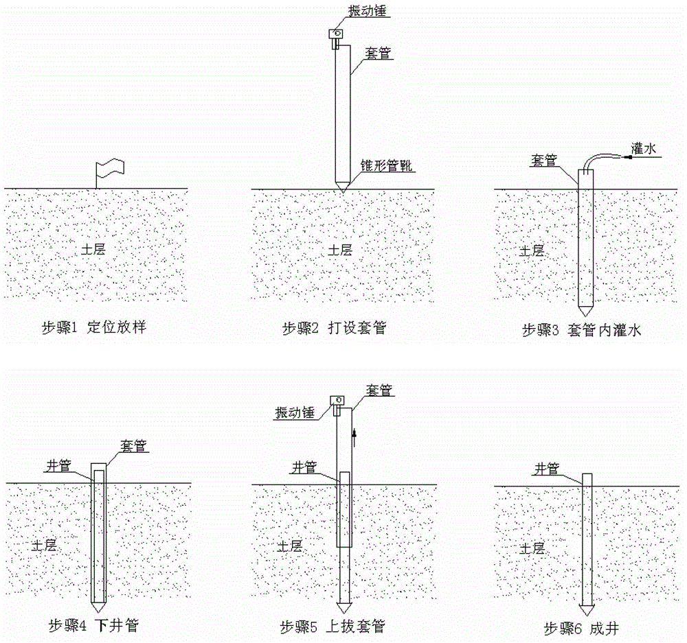
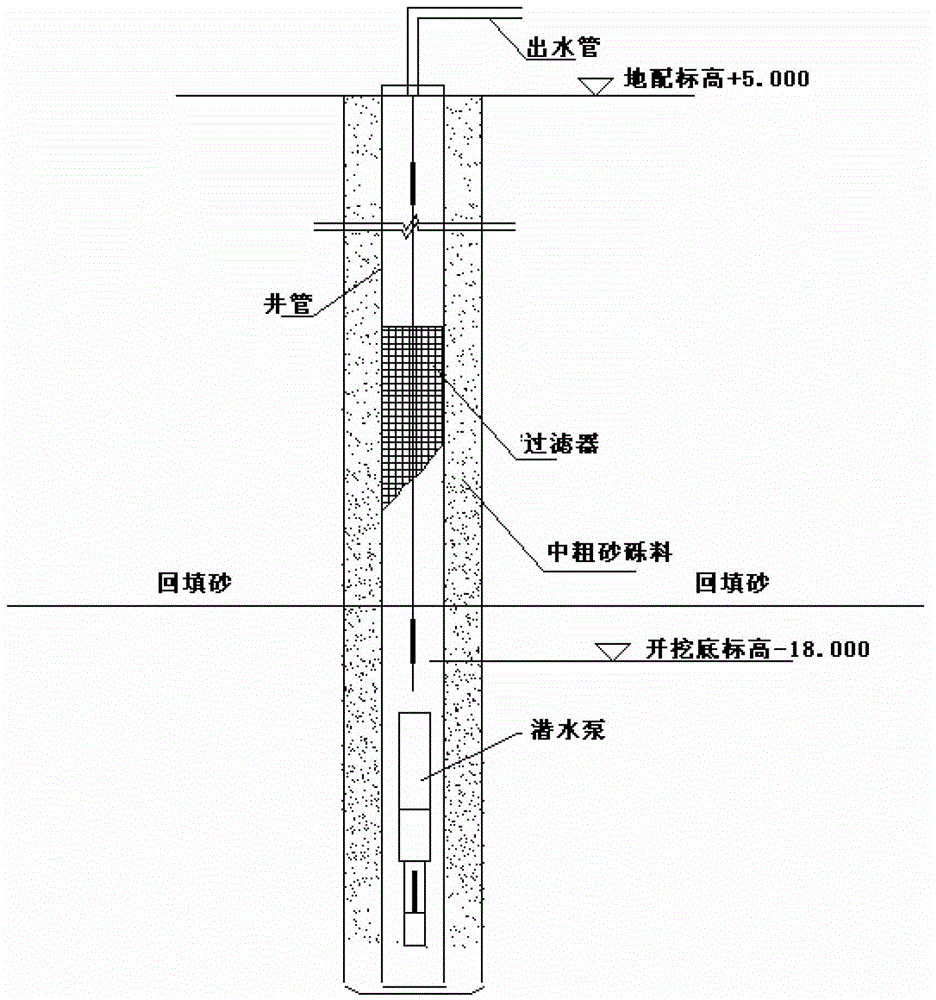
[0032] refer to figure 1 and figure 2 , a construction method of a dewatering well, comprising the following steps:

[0033] (1) Positioning and stakeout

[0034] Use the GPS positioning system or other measurement and positioning methods combined with the stakeout coordinates of the design drawings to stake out and insert flags for identification, and then place tapered pipe boots on the corresponding positions of the sample points;

[0035] (2) Setting up casing

[0036] Use a crane to lift the hydraulic vibratory hammer, the vibratory hammer clamps the casing, inserts the casing into the conical pipe shoe on the stakeout point, and is fixedly connected by the steel hoop of the conical pipe shoe, and then opens the vibratory hammer to conn...


PUM


Abstract

The invention discloses a construction method of a precipitation well, which comprises the following steps of: (1) positioning and sampling; (2) arranging a sleeve pipe; (3) filling water in the sleeve pipe; (4) placing a well pipe; (5) upwards pulling the sleeve pipe; and (6) forming a well, and keeping zero emission (treatment) of sludge. The slurry is not in need to protect a wall when a hole is formed, and the sleeve pipe is directly arranged to the designed bottom elevation; and in the process of forming the hole, the sludge influx can be effectively prevented, the well pipe can be directly placed without cleaning or washing the hole after the hole is formed. The entire procedure does not need the slurry, so that the effect of zero emission of the slurry is achieved. The construction method is fewer in procedure and high in working efficiency. The improved technique reduces the procedures of cleaning the hole, washing the well, and the like, and the whole well forming procedure only spends 1-1.5 hours, so that the working efficiency is largely improved. The procedure is simplified, the required assistant workers are largely reduced, and the labor cost is also decreased.

Description

technical field [0001] The invention relates to a well drilling method, in particular to a construction method of a dewatering well. Background technique [0002] The key to well completion in the existing technology lies in the reasonable selection of the specific gravity of the mud when the hole is formed. If the specific gravity of the prepared mud is too large, the viscosity will also increase, the mud skin on the well wall will thicken, and the open hole drilling time will be maintained longer, so that there is enough time Casing, but it is difficult to dilute the mud, and it takes a long time to wash the well, and it is even difficult to flush and the wellbore is scrapped, so it takes time to prepare repeatedly according to the site conditions. Furthermore, the work efficiency is low (it takes 3-4 hours to form a hole, if the power of the drilling rig is low or the workers are not skilled in operation, the time will be longer; it takes about 2 hours to clean the hole) ...

Claims


Application Information

Patent Timeline
Patent Type & Authority Applications(China)
IPC IPC(8): E02D19/10E02D11/00
Inventor 黎亚舟孙伟明沈永兴刘海青王伟黄超苏根明莫日雄张奎包益平
Owner CCCC THIRD HARBOR ENG
Why Eureka
Try Eureka