
Reservoir fluid recognizing method

A fluid identification and reservoir technology, applied in earthwork drilling and production, wellbore/well components, etc., can solve problems such as difficult to realize quantitative identification of oil, gas and water, polarization, difference spectrum signal of water layer, etc.

Active Publication Date: 2013-02-06
PETROCHINA CO LTD
View PDF5 Cites 14 Cited by
  • Summary
  • Abstract
  • Description
  • Claims
  • Application Information

AI Technical Summary

Problems solved by technology

Due to the complex pore structure, it is often encountered that the water signal in the pores cannot be completely polarized in a short waiting time. At this time, the water layer has a phenomenon of differential spectrum signals, which leads to misinterpretation of the oil layer by the water layer and reduces the coincidence rate of NMR logging. (See "Numerical Simulation of Nuclear Magnetic Resonance Logging Time-domain Analysis Method and Analysis of Influencing Factors" by Xie Ranhong, Xiao Lizhi, etc. in the journal "Journal of Geophysics" in August 2011, which records that the short waiting time of 1S cannot make large holes The water in the water is completely polarized, resulting in difference spectrum signals in the water layer, resulting in logging interpretation errors); for the shift spectrum method, which mainly relies on empirical methods, it is still quite far-fetched in theory, and it is difficult to realize the quantitative analysis of oil, gas and water in practical applications. Identification (see "Several Important Issues in the Application of Nuclear Magnetic Resonance Logging in my country" written by Xiao Lizhi in the "Logging Technology" magazine in October 2007, which records the limitations of spectral shifting technology based on experience)

Method used


Image

  • Reservoir fluid recognizing method
  • Reservoir fluid recognizing method
  • Reservoir fluid recognizing method

Examples


Embodiment Construction

[0020] In order to make the purpose, technical solutions and advantages of the embodiments of the present invention more clear, the embodiments of the present invention will be further described in detail below in conjunction with the accompanying drawings. Here, the exemplary embodiments and descriptions of the present invention are used to explain the present invention, but not to limit the present invention.

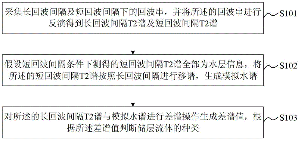
[0021] Such as figure 1 As shown, the present invention provides a reservoir fluid identification method, and the reservoir fluid identification method includes:

[0022] Step S301: Use the dual TE mode under long waiting time to log the reservoir, collect echo trains under long echo interval and short echo interval, and invert the echo train to obtain long echo Interval T2 spectrum and short echo interval T2 spectrum.

[0023] In the above steps, the long waiting time is usually 10-13s to ensure that the measured reservoir fluid is completely polarized; the short e...


PUM


Abstract

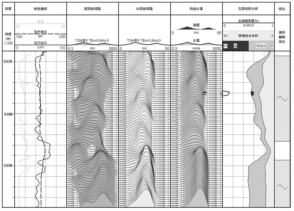
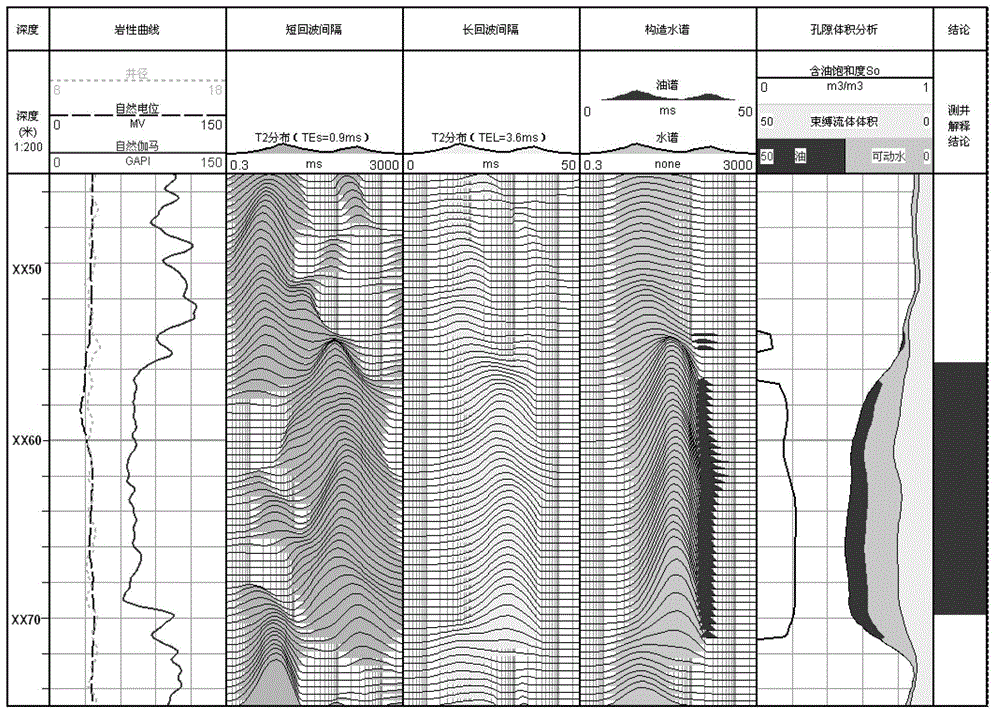
The invention provides a reservoir fluid recognizing method. The reservoir fluid recognizing method includes: logging a reservoir layer by double TE modes in long wait time, acquiring echo strings in long echo interval and short echo interval, inverting the echo strings to obtain a long echo interval T2 spectrum and a short echo interval T2 spectrum; shifting the short echo interval T2 spectrum to generate a simulating water spectrum according to the long echo interval supposing the short echo interval T2 spectrum measured under the condition of the short echo interval is all water course; subjecting the long echo interval T2 spectrum and the simulating water spectrum to spectrum differencing to generate a differential spectrum delta M, and judging the type of the reservoir fluid according to the differential spectrum delta M. Supposing the T2 spectrum under the condition of the short echo interval as the water spectrum, the long echo interval T2 spectrum is simulated, and oil gas water fluid in a pore medium in the reservoir layer can be recognized by subjecting the measured T2 spectrum and the simulated water spectrum at the long echo interval to differential spectrum processing and analyzing.

Description

technical field [0001] The invention relates to petroleum logging technology, in particular to a reservoir fluid identification method. Background technique [0002] In the field of oil exploration and logging technology, nuclear magnetic resonance logging technology is an important reservoir evaluation and fluid identification technology, which can provide reservoir information such as porosity, permeability, irreducible water saturation and pore distribution independent of lithology. Reservoir fluid properties can also be identified by difference spectrum method and shift spectrum method. When oil and water exist in the reservoir, the distribution of transverse relaxation time T2 is the comprehensive contribution of various fluids and pore structures. Due to the influence of porous media, oil-water NMR T2 signals overlap, which greatly increases the difficulty of oil-water identification. [0003] In the prior art, when NMR logging is used for oil-water identification, di...

Claims


Application Information

Patent Timeline
IPC IPC(8): E21B49/08
Inventor 胡法龙周灿灿李潮流徐红军李长喜
Owner PETROCHINA CO LTD
Learn More