Fan rotating speed control circuit

A technology for controlling circuit and fan speed, applied in pump control, non-variable-capacity pump, machine/engine, etc., can solve the problems of large volume, users changing the rotor speed, and the inability of a single drive circuit to meet the wind speed, etc. Design streamlined effects

Active Publication Date: 2013-02-06
SUNONWEALTH ELECTRIC MACHINE IND
View PDF7 Cites 1 Cited by
  • Summary
  • Abstract
  • Description
  • Claims
  • Application Information

AI Technical Summary

Problems solved by technology

[0004] However, since the modulating resistor 922 is a temperature control resistor, the existing speed control circuit can only adjust the speed of the rotor according to the ambient temperature measured by the temperature changing resistor, and cannot allow the user to change the rotor according to other requirements. Speed, and as far as the supplier of the fan motor is concerned, it is impossible to meet the individual needs of different buyers for the individual wind speed with a single drive circuit; It is for the user to adjust the resistance value of the variable resistor 922 according to the needs, but because the general knob-type variable resistor has a large volume, it will make it difficult to further miniaturize the motor / fan equipped with this speed control circuit

Method used


Image

  • Fan rotating speed control circuit
  • Fan rotating speed control circuit
  • Fan rotating speed control circuit

Examples


Embodiment Construction

[0037] In order to make the above-mentioned and other objects, features and advantages of the present invention more comprehensible, the preferred embodiments of the present invention are specifically cited below, together with the accompanying drawings, and are described in detail as follows:

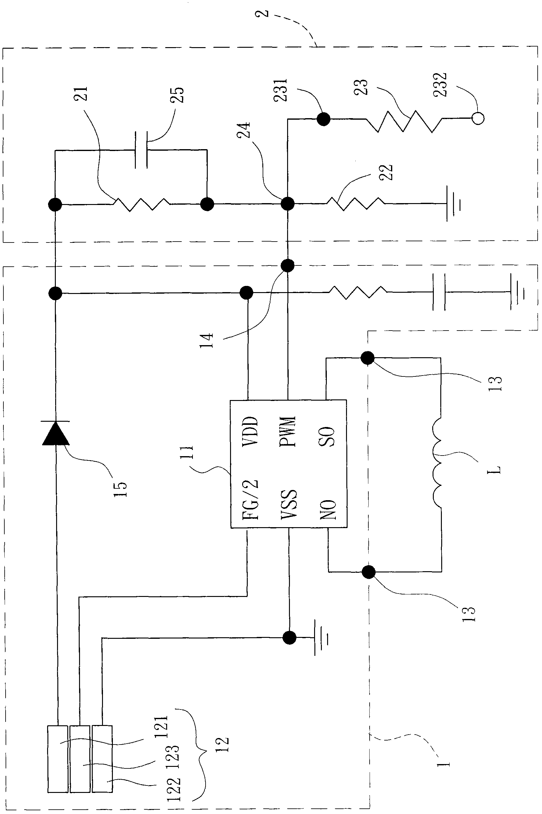
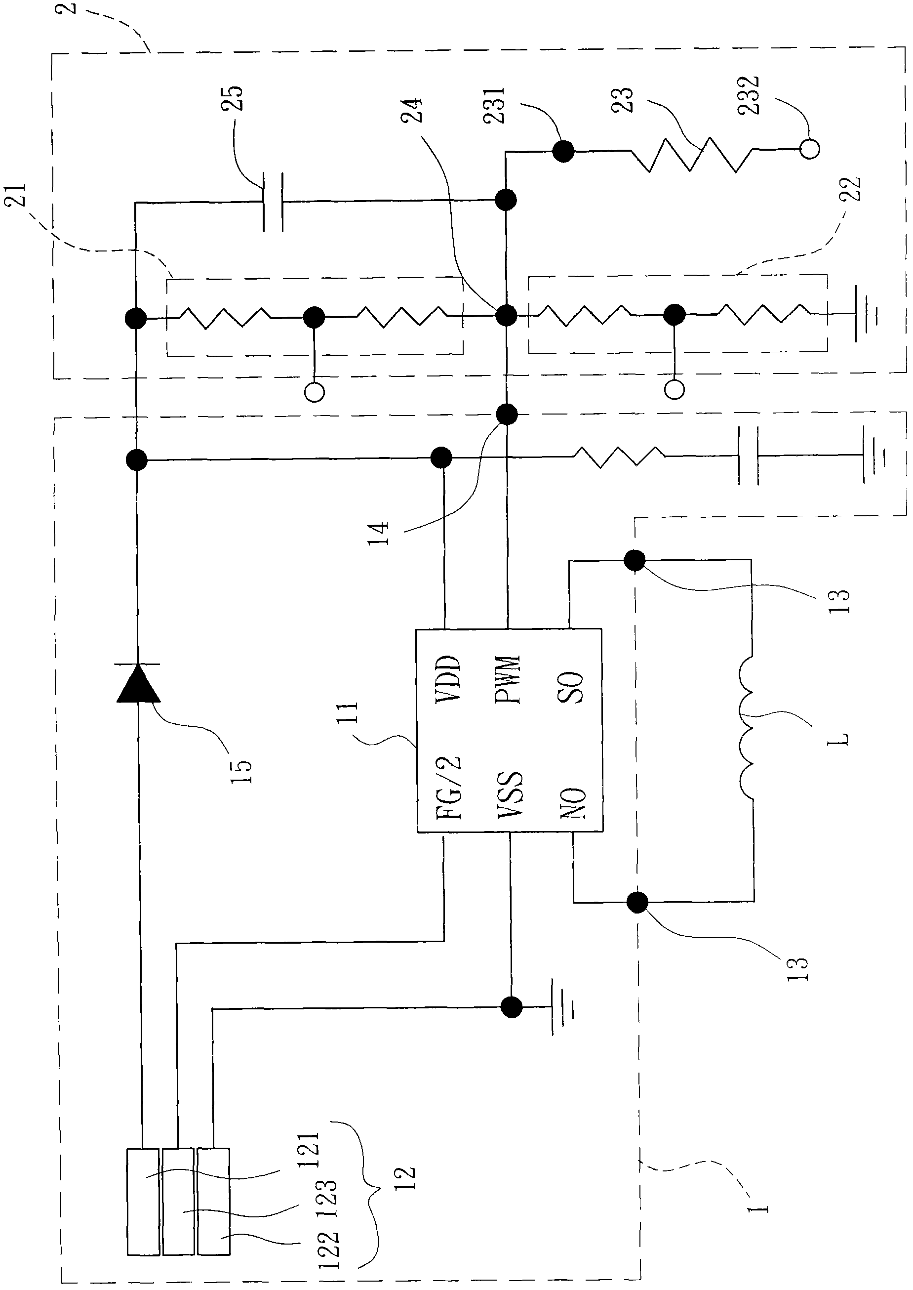
[0038] Please refer to figure 2 As shown, it shows the first embodiment of the fan speed control circuit of the present invention, and the fan speed control circuit is used to connect and control the driving current in the stator winding L of a fan motor to drive the fan motor to run. The fan speed control circuit includes a speed control drive unit 1 and a speed control unit 2, wherein the speed control drive unit 1 is connected to the stator winding L, and the speed control unit 2 is connected to the speed control drive unit 1, and the speed control The unit 2 can output a speed regulation voltage for the speed control drive unit 1 to output the driving current corresponding to the ...


PUM


Abstract

The utility model relates to a fan rotating speed control circuit, which comprises a speed control driving unit and a speed regulating unit, wherein the speed control driving unit is provided with a driving element, a stator driving port and a power supply / signal transmission port, the stator driving port is connected with the driving element and outputs driving current generated by the driving element, the power supply / signal transmission port is connected with the driving element and is provided with a high-level end and a grounding end, the speed regulating unit is provided with a first voltage dividing element and a second voltage dividing element which are connected in series between the high-level end and the grounding end, a voltage output port is formed by series connection points between the first voltage dividing element and the second voltage dividing element and is electrically connected to the driving element, the speed regulating unit is additionally provided with a speed regulating resistor, the first endpoint of the speed regulating resistor is connected with the voltage output port, and the second endpoint of the speed regulating resistor can be connected to the high-level end and the grounding end or can be in suspension connection. The rotating speed of a fan motor provided with the fan rotating speed control circuit provided by the utility model can be easily and fast changed.

Description

technical field [0001] The invention relates to a fan speed control circuit, in particular to a fan speed control circuit which can be quickly and conveniently adjusted by the user and is easy to be miniaturized. Background technique [0002] Please refer to figure 1 As shown, it is the existing speed control circuit disclosed in Taiwan Invention No. I302400 "Motor Speed ​​Control Device". The existing speed control circuit includes a driving element 91 , a speed regulating unit 92 and a stator winding 93 . The driving element 91 has a voltage regulating terminal 911 connected to the speed regulating unit 92, and the driving element 91 also has a stator driving port 912 connected to the stator winding 93, wherein the driving element 91 is based on the voltage regulating terminal 911 The voltage level is output from the stator driving port 912 to the stator winding 93 to drive a rotor to run at a speed corresponding to the voltage level of the voltage regulating terminal 91...

Claims


Application Information

Patent Timeline
Patent Type & Authority Applications(China)
IPC IPC(8): F04D27/00
Inventor 郭启宏郭宗根柯立勇
Owner SUNONWEALTH ELECTRIC MACHINE IND
Why Eureka
Try Eureka