AMT (automatic mechanical transmission) gear position calibration method for hybrid automobiles

A technology of hybrid power and calibration method, which is applied in the direction of transmission control, components with teeth, belt/chain/gear, etc., to achieve the effect of reducing calibration time and selecting accurate and optimized gear positions

Active Publication Date: 2015-02-25
CHANGSHA CRRC INTELLIGENT CONTROL & NEW ENERGY TECH CO LTD
View PDF8 Cites 0 Cited by
  • Summary
  • Abstract
  • Description
  • Claims
  • Application Information

AI Technical Summary

Problems solved by technology

[0004] The invention provides a method for calibrating AMT gear positions of hybrid electric vehicles. The method for calibrating AMT gear positions based on an angle sensor mainly solves the calibration of gear positions when the AMT automatic transmission of a parallel hybrid electric vehicle is shipped from the factory, and the use of The problem of gear position correction during the process

Method used


Image

  • AMT (automatic mechanical transmission) gear position calibration method for hybrid automobiles
  • AMT (automatic mechanical transmission) gear position calibration method for hybrid automobiles
  • AMT (automatic mechanical transmission) gear position calibration method for hybrid automobiles

Examples


Embodiment 1

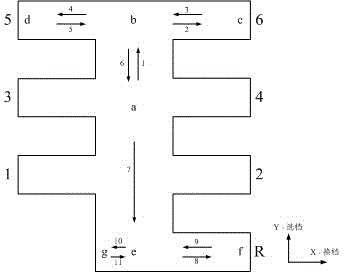
[0018] Embodiment 1: The realization method of the AMT gear position calibration of the 6-speed gearbox of a hybrid electric vehicle is as follows figure 2 Shown:

[0019] A. The calibration method of each gear limit position:

[0020] Step 1. When the calibration starts, the gearbox is in the neutral position. At this time, the selection and shift motors are at point a. Record the current selection and shift motor angles. ;

[0021] Step 2, keep the position of the shift motor unchanged, and find the direction of gear selection The limit position of can reach point b:

[0022] 1) The target position of the gear selection motor increases by 1 step, and enters 2) after the execution is completed.

[0023] 2) assume Indicates the current gear selection motor position, Indicates the target position of the current gear selection motor, Indicates the control accuracy of the gear selection motor, . if , then the gear selection motor can reach the new target positio...

Embodiment 2

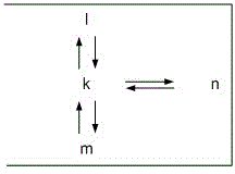
[0046] Embodiment 2: gear position optimization method

[0047] On the basis of the above position coordinates, accurate switching of each gear of the AMT can be realized. However, due to the limited coordinate information of the actually obtained position points, it cannot reflect all gear information. At the same time, the structural size of the gearbox comes from the average data of batch products. Considering the differences between different gears and different gearbox entities, the AMT in gear In the process of bit switching, there may be phenomena such as stuck, not in place, etc., so it is necessary to further adjust and optimize on the basis of the above values, and re-find the appropriate position coordinates for each specific gear. The new gear position needs to be in the middle of the gear recognition range and closer to the shift limit position. Compared with the previous gear position, the new position is more reliable and easy to reach. By finding the area of ​...


PUM


Abstract

The invention provides a six-gear AMT (automatic mechanical transmission) gear position calibration method for hybrid automobiles. The angular-transducer-based AMT gear position calibration method is mainly used for gear position calibration in delivery test of AMT automatic transmissions of parallel hybrid passenger vehicles and gear position correction in use. Optimal control of gear position query paths is realized by setting up a gear coordinate system based on gear selecting and shifting motor angles, and automatic calibration and correction of all gear positions can be realized on the basis of known limited target point positions and AMT interior structural characteristics. All gear positions are calibrated by the aid of least extreme coordinate point information, calibration time is shortened, accuracy and optimization in gear position selection are guaranteed, errors in reverse gear selection can be prevented, and accordingly running safety of automobiles is guaranteed.

Description

technical field [0001] The invention is mainly applied in the technical field of hybrid electric vehicles, and provides an AMT gear position calibration method for hybrid electric vehicles. Background technique [0002] Due to its simple structure and mature technology, hybrid electric buses have been widely used in the field of new energy vehicles and belong to the country's emerging industries. However, when shifting gears in a hybrid electric bus, due to the driver's proficiency and driving skills, the engine of the vehicle often works in an unstable working state, which affects the fuel-saving efficiency of the vehicle. AMT automatic transmission can solve the above problems very well. By automatically adjusting the gear position of the vehicle, it can eliminate the differences in driving skills and proficiency of different drivers, reduce driver fatigue and reduce fuel consumption. The premise of gear shifting in AMT automatic transmission is the correct acquisition of...

Claims


Application Information

Patent Timeline
Patent Type & Authority Patents(China)
IPC IPC(8): F16H61/00F16H63/42
Inventor 宋超谢勇波石魏裴海灵王文明罗宏亮
Owner CHANGSHA CRRC INTELLIGENT CONTROL & NEW ENERGY TECH CO LTD
Why Eureka
Try Eureka