Efficient distribution dryer

A drying machine and fabric technology, applied in the direction of dryers, drying, progressive dryers, etc., can solve the problems of high pressure on the fabric, affecting the quality of the fabric, and uneven distribution of hot air, so as to prevent local overheating and pressure Deformation, guaranteed drying quality, and improved drying efficiency

Inactive Publication Date: 2013-02-06
WUJIANG KESHIDA TEXTILE
View PDF7 Cites 40 Cited by
  • Summary
  • Abstract
  • Description
  • Claims
  • Application Information

AI Technical Summary

Problems solved by technology

Since there is usually only one air inlet, and it is located in the center of the top of the shell, the hot air in the center of the shell cavity and around it is unevenly distribute

Method used


Image

  • Efficient distribution dryer
  • Efficient distribution dryer

Examples


Embodiment Construction

[0015] The present invention will now be further described in detail in conjunction with the accompanying drawings and embodiments. These drawings are all simplified schematic diagrams, only illustrating the basic structure of the present invention in a schematic manner, so it only shows the composition related to the present invention.

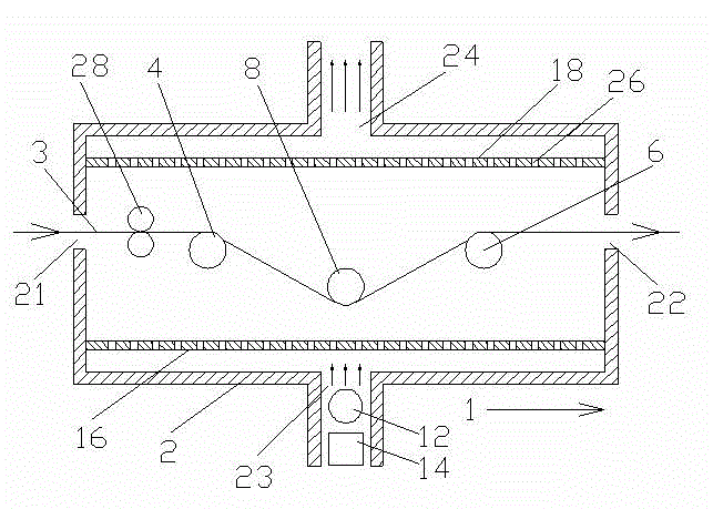
[0016] Such as Figure 1-2 As shown, a high-efficiency cloth dryer in the present invention includes a box-type housing 2, and the two ends of the housing 2 are respectively provided with a cloth inlet 21 and a cloth outlet 22, and the end with the cloth inlet 21 is the cloth inlet end. The end with the cloth outlet 22 is the cloth outlet; the bottom of the casing 2 is provided with an air inlet 23, and the top is provided with an air outlet 24, and the air inlet 23 and the air outlet 24 are aligned. A cloth conveying mechanism is arranged in the inner cavity of the housing 2 . The cloth conveying mechanism includes a cloth feed roller 4 loc...


PUM


Abstract

The invention relates to an efficient distribution dryer which comprises a box housing. Two ends of the housing are provided with a cloth inlet and a cloth outlet. The housing is provided with an air inlet at the top and an air outlet at the bottom, or provided with an air inlet at the bottom and an air outlet at the top. A distribution conveying mechanism is disposed in an inner cavity of the housing. A heating pipe and a bower outside the heating pipe are disposed at the air inlet. The efficient distribution dryer is characterized in that transversely extending partitions are disposed in the inner cavity of the housing, and a plurality of intake through holes are arranged on the partitions in directions, along the distribution conveying direction and transversely perpendicular to the distribution conveying direction. The partitions with intake through holes are disposed in the efficient distribution dryer and disperse hot air from the single air inlet, so that local superheating and compressive deformation are prevented, drying quality is guaranteed and overall drying efficiency is also improved.

Description

technical field [0001] The invention relates to a drying device in the textile field, in particular to a cloth drying device. Background technique [0002] In the production of fabrics, especially the production of fabrics using water jet looms, since the formed fabrics obtained contain relatively high moisture content, drying equipment is finally needed to dry and set the shape. At present, a general-purpose dryer includes a box-type shell, with an air inlet on the top of the shell, an air outlet on the bottom, a heating pipe and a blower on the outside of the air inlet, and the hot air is longitudinally transported to the inner cavity of the shell through the blower and the heating pipe. , the cloth passes through the dryer shell transversely, and is dried by hot air in the inner cavity of the shell. Since there is usually only one air inlet, and it is located in the center of the top of the shell, the hot air in the center of the shell cavity and around it is unevenly di...

Claims


Application Information

Patent Timeline
IPC IPC(8): F26B13/08F26B25/08
Inventor 庄郁峰
Owner WUJIANG KESHIDA TEXTILE
Why Eureka
Try Eureka