
Device for testing the response characteristics of metal oxide samples under steep front pulses

A technology of steep frontier pulse and test device, applied in the direction of measurement device, test circuit, test dielectric strength, etc., can solve the problems of large stray parameters, complex loop, etc., and achieve short wave head time, large current peak value, and wide range. Effect

Active Publication Date: 2015-09-23
CHINA ELECTRIC POWER RES INST +2
View PDF4 Cites 0 Cited by
  • Summary
  • Abstract
  • Description
  • Claims
  • Application Information

AI Technical Summary

Problems solved by technology

[0004] In the existing test technology, the pulse voltage is generally generated by the Marx generator and applied to the metal oxide sample, but this kind of experimental circuit is complicated, the stray parameters are large, and it is difficult to generate a very steep current rising edge

Method used


Image

  • Device for testing the response characteristics of metal oxide samples under steep front pulses
  • Device for testing the response characteristics of metal oxide samples under steep front pulses
  • Device for testing the response characteristics of metal oxide samples under steep front pulses

Examples


Embodiment 1

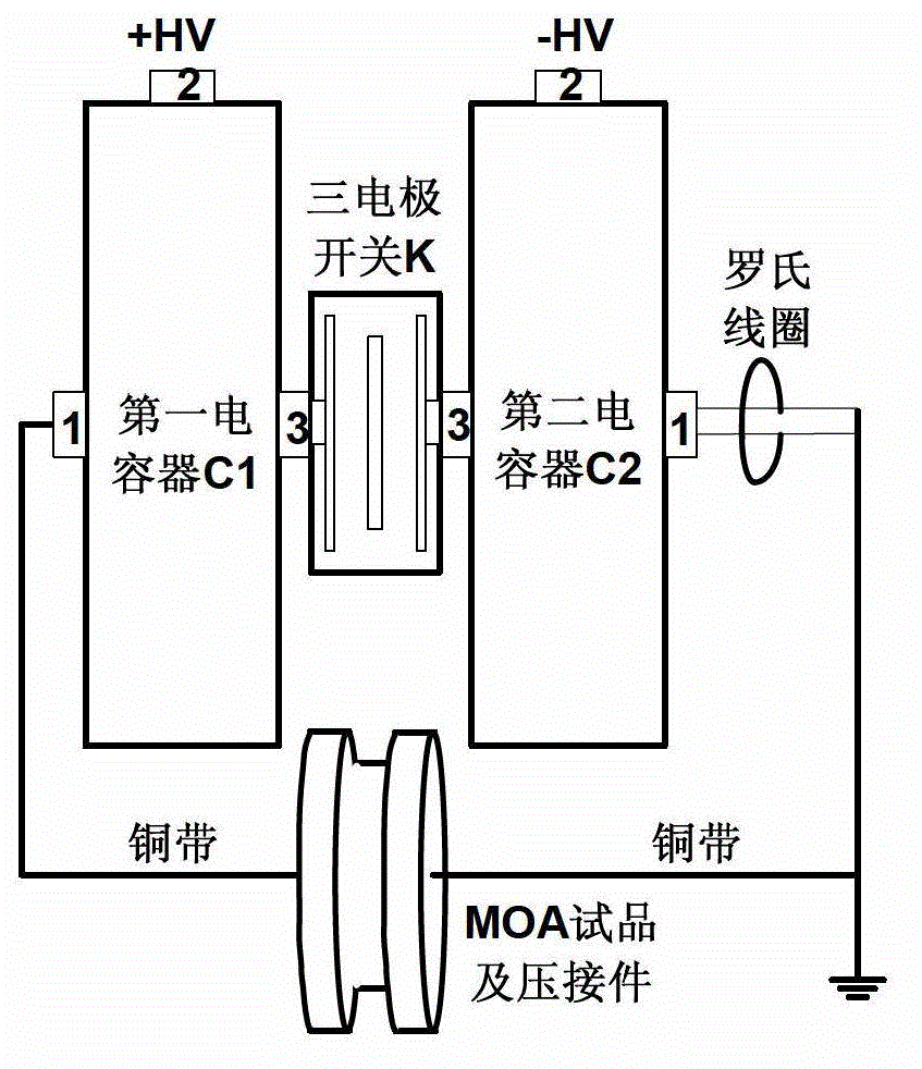
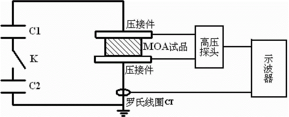
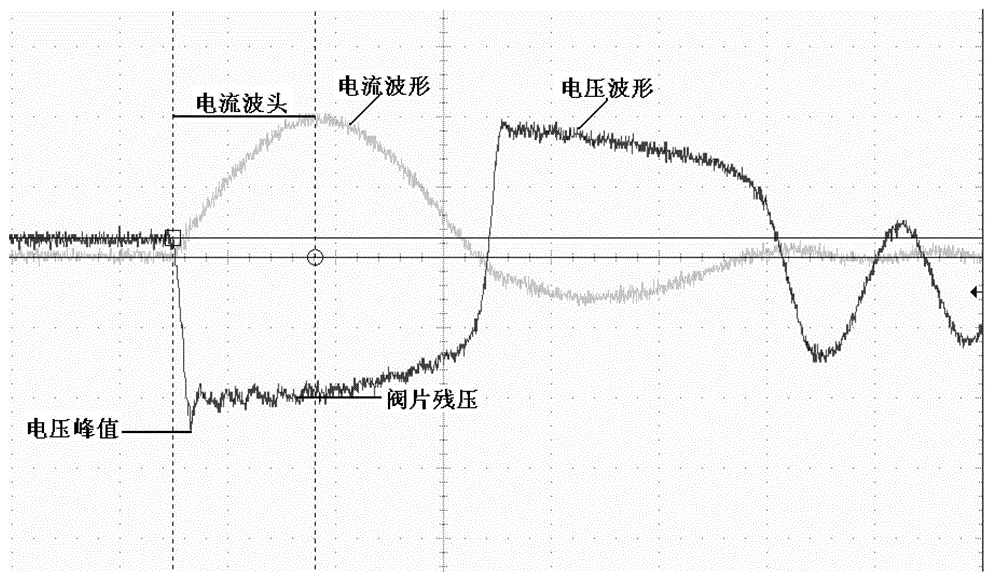
[0038] The MOA sample that adopts in an embodiment of the present invention is MOA resistive sheet QA22, and this example is to measure the volt-ampere characteristic of resistive sheet QA22 under the steep wave, two capacitors C of the steep wave leading edge current pulse generating device 1 、C 2 The capacitor value is 40nF, choose to fill SF 6 Gas three-electrode switch K, the gap distance is about 4mm, the gas pressure is -0.1MPa~0.1MPa, and the charging voltage of the DC power supply U is 10kV~100kV. The steep front current pulse generating device is placed in the air, according to figure 1 As shown, the resistor QA22 is connected in the circuit, and the current and voltage waveforms on the resistor are shown in image 3 , the current is a decaying oscillatory wave with a period of about 336ns and a rise time of the wave head of 80ns.

[0039] By changing the charging voltage of the DC power supply U, the generated current ranges from 610A to 10kA, measured the current...

Embodiment 2

[0044] The MOA sample that adopts in another embodiment of the present invention is MOA resistor sheet RB41, and this example is to measure the volt-ampere characteristic of MOA resistor sheet RB41 under the steep wave, two capacitors C of the steep wave front current pulse generating device 1 、C 2 The capacitance value of each capacitor is 40nF, the three-electrode switch K filled with air is selected, the gap distance is about 1mm, the gas pressure is -0.1MPa~0.1MPa, and the charging voltage of the DC power supply U is 10kV~50kV. The steep front current pulse generating device is placed in the air, according to figure 1 As shown, the resistance piece RB41 is connected in the circuit, and the current and voltage waveforms on the resistance piece are shown in Figure 5 , the current is a decaying oscillatory wave with a period of about 283ns and a rise time of the wave head of 60ns.

[0045] By changing the charging voltage of the DC power supply U, the generated current ran...


PUM


Abstract

Provided is a device for testing the response characteristic of a metal oxide sample under steep-front pulses, comprising: a steep-wave-front current pulse generating device for generating a steep-wave-front current waveform; and a test instrument for testing the current and voltage waveform of the sample. The sample is connected in a loop formed by the steep-wave-front current pulse generating device; and a DC power supply is used to charge two capacitors in the steep-wave-front current pulse generating device to break down a tri-electrode switch, so as to test the response characteristic of the metal oxide sample under the steep-front pulse. The test device reduces loop inductance by employing a capacitor-switch integrated structure, minimizes the loop inductance by employing a mechanism having the capacitors compactly wrapped by copper strips, thus ensuring sufficient current amplitude and steep rising edge, and clearly improving the residual voltage of a valve under a steep wave with the increase of a steep-wave-front current.

Description

technical field [0001] The invention belongs to the field of power system overvoltage, in particular to a device for testing the response characteristics of metal oxide samples under steep front pulses. Background technique [0002] Experimental research shows that the gas-insulated metal-enclosed switchgear (GIS) isolation switch operation will generate high amplitude and steep very fast transient overvoltage (VFTO), which will affect the secondary equipment of GIS and its connected equipment insulation and shell connection. operation has a significant impact. At present, the method of GIS isolating switch with damping resistor proposed by Toshiba is widely used to suppress VFTO, and it has been well applied in practice. Both Changzhi Station and Nanyang Station of my country's UHV AC test demonstration project have adopted this scheme. Tsinghua University tried to install a high-frequency magnetic ring on the GIS high-voltage guide rod to suppress VFTO. A large number of ...

Claims


Application Information

Patent Timeline
Patent Type & Authority Patents(China)
IPC IPC(8): G01R31/00
CPCG01R31/14G01R31/00H03K3/55G01R31/1227
Inventor 颜湘莲陈维江张乔根李志兵刘轩东王浩李晓昂
Owner CHINA ELECTRIC POWER RES INST
Learn More