Finger board

A finger-pressing plate and pressing-plate technology, which is applied to the finger-pressing plate field of a fingerprint identification device, can solve problems such as difficulty in assembling light-emitting elements, and achieve the effects of improving the fingerprint identification rate, reducing the thickness and simplifying the assembly process.

Inactive Publication Date: 2013-02-06
GINGY TECH
View PDF6 Cites 18 Cited by
  • Summary
  • Abstract
  • Description
  • Claims
  • Application Information

AI Technical Summary

Problems solved by technology

[0005] The present invention provides an acupressure plate to solve the problem that the existing light guide plate guides the incident light to travel according to the principle of total reflection, which makes it difficult to assemble the light-emitting elements.

Method used


Image

  • Finger board
  • Finger board
  • Finger board

Examples


Embodiment Construction

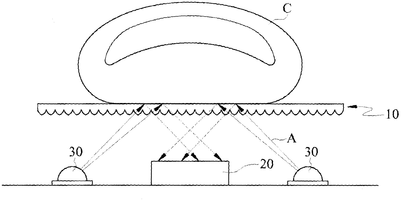
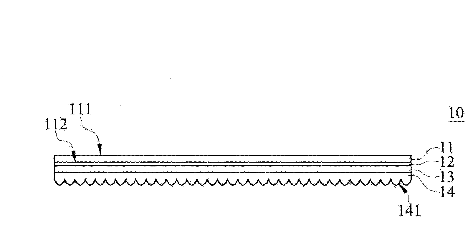
[0031] Please refer to figure 1 and figure 2 , figure 1 Shown is a schematic structural diagram of a fingerprint recognition device of an embodiment, figure 2 Shown is a structural cross-sectional view of the finger-pressing board of an embodiment.

[0032] The finger board 10 according to an embodiment of the present invention is used in a fingerprint recognition device, and the fingerprint recognition device includes a finger board 10 (Finger Board), an imaging device 20 and at least one light emitting device 30 . When a finger C is placed on the acupressure board 10 , the light emitting element 30 can be driven to emit a light A toward the acupressure board 10 . The light A enters the acupressure board 10 and irradiates the finger C, and produces a fingerprint pattern with light and dark contrast, so that the image capturing element 20 achieves the effect of capturing and identifying fingerprints. Wherein, the path of light A in the drawings is just an example of one ...


PUM


Abstract

A finger board for a finger to press including a board layer and a micro-structure layer is disclosed. The board layer has a first refractive index, and has a first board surface and a second board surface opposite to each other. The first board surface is used for the finger to press. The micro-structure layer has a second refractive index different from the first refractive index, and is disposed on the second board surface. Therefore, a light ray emitted from the micro-structure layer to the first board surface can be reflected and scattered on the first board surface, so as to uniformly distribute energy.

Description

technical field [0001] The invention relates to a finger-pressing board, in particular to a finger-pressing board used for a fingerprint identification device. Background technique [0002] For example, in US Pat. No. 5,177,802, an acupressure device in the prior art mainly includes an imaging element, a light guide plate disposed above the imaging element, and two light emitting elements disposed on both sides of the light guide plate. When the light-emitting element emits light, the light guide plate can guide the incident light to project to the finger according to the principle of total reflection, and then reflect to the image-taking element to achieve the effect of fingerprint recognition. [0003] However, since the light guide plate guides the incident light to travel according to the principle of total reflection. Therefore, during the assembly process, the incident angle between the light-emitting element and the light guide plate must be precisely adjusted to eff...

Claims


Application Information

Patent Timeline
Patent Type & Authority Applications(China)
IPC IPC(8): G06K9/00A61B5/117
CPCG06K9/00046G06V40/1324G06V10/40
Inventor 吴建兴周荣宗
Owner GINGY TECH
Why Eureka
Try Eureka