Helical multi-gap high-frequency resonator device and beamforming and accelerating method

A high-frequency resonance, multi-gap technology, applied in accelerators, electrical components, etc., can solve the problems of difficulty, insufficient electromagnetic analysis, large size of resonators, etc., and achieve the effect of improving efficiency and effect

Active Publication Date: 2016-01-13
INST OF MODERN PHYSICS CHINESE ACADEMY OF SCI
View PDF8 Cites 0 Cited by
  • Summary
  • Abstract
  • Description
  • Claims
  • Application Information

AI Technical Summary

Problems solved by technology

Due to the low operating frequency, the generally designed resonators are relatively large, which causes great inconvenience to the cost of the project and the integration of the overall system
At present, several laboratories in the world have carried out research on helical structures. Among them, TRIUMF in Canada and GSI in Germany have similar research, but they are all limited to the study of single-arm structures with double gaps. Although this structure solves the problem of resonator The oversize problem, but the efficiency of the accelerator is not very high due to the excessive power consumption of the overly long inner bar
[0003] This type of structure is rarely used in China, mainly due to the lack of machining capabilities at present, the precision guarantee for the spiral structure does not meet the application of accelerators, and the electromagnetic analysis of this structure is insufficient, so it cannot be used in impedance matching, especially for multiple It is difficult to ensure the consistency of impedance matching in the case of circuit coupling

Method used


Image

  • Helical multi-gap high-frequency resonator device and beamforming and accelerating method
  • Helical multi-gap high-frequency resonator device and beamforming and accelerating method
  • Helical multi-gap high-frequency resonator device and beamforming and accelerating method

Examples


Embodiment 1

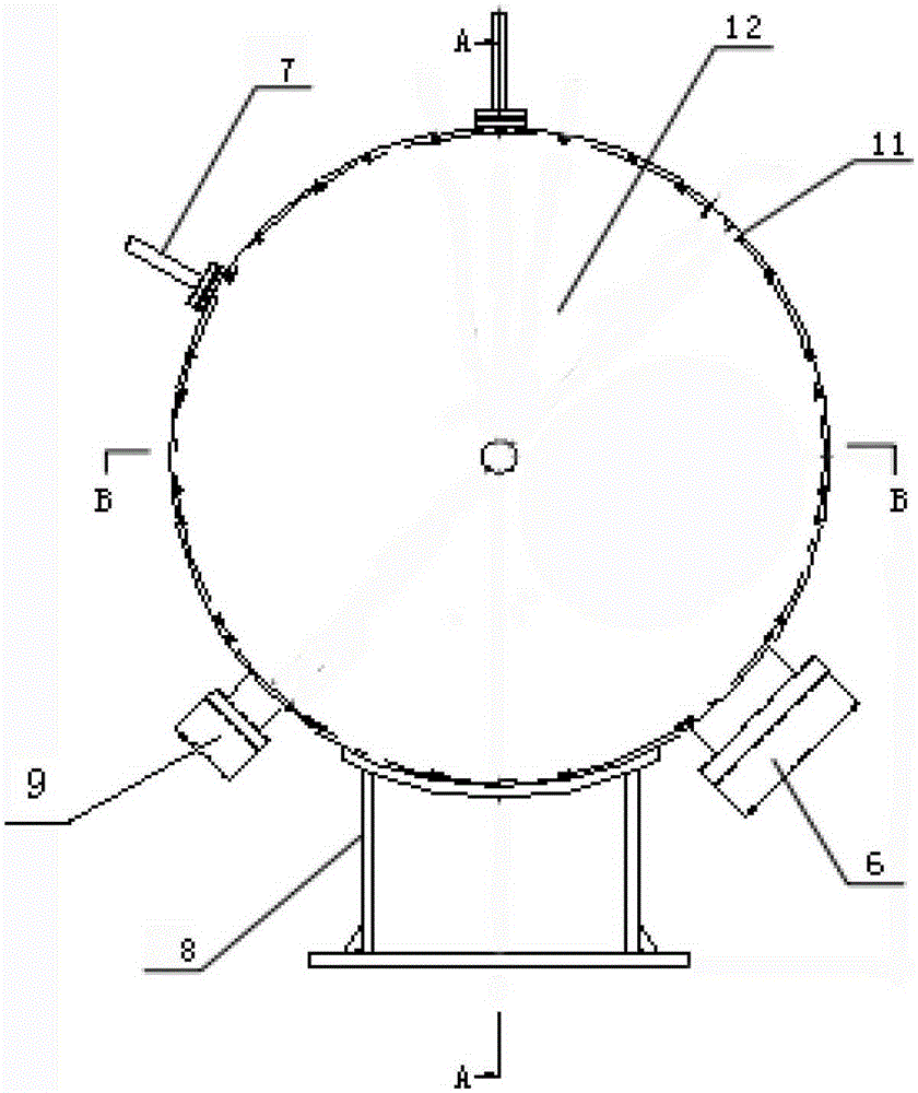
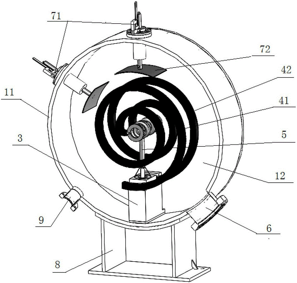
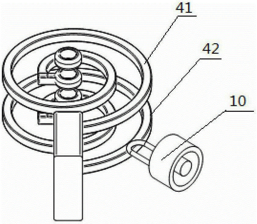
[0034] Example 1: see figure 1 , figure 2 , image 3 , Figure 4 , Figure 5As shown, a spiral multi-gap high-frequency resonance device includes a cavity on which a coupler bracket 6 is arranged. The cavity is composed of a cylindrical outer wall 11 and two circular side walls 12, Cylindrical outer wall 11 and two circular sidewalls 12 have surrounded airtight cavity, and the center of described two circular sidewalls 12 is provided with first drift tube 21 and the 5th drift tube 25, in cavity There is also a support seat 3 inside, the support seat 3 supports the second drift tube 22 and the fourth drift tube 24 in the cavity through the first helical arm 41 and the second helical arm 42, and the support seat 3 is also provided with There is a support rod 5, a third drift tube 23 is arranged on the top of the support rod 5, the first drift tube 21, the second drift tube 22, the third drift tube 23, the fourth drift tube 24, the fifth drift tube 25 coaxially arranged, th...

Embodiment 2

[0038] Embodiment 2: as Image 6 As shown, the present invention also provides a bunching method of the spiral multi-gap high-frequency resonance device: comprising the following steps,

[0039] (1) Resonance: The power source injects power into the spiral multi-gap high-frequency resonance device. When the power source is consistent with the power of the spiral multi-gap high-frequency resonance device, the power source can excite the spiral multi-gap high-frequency resonance device. In the cavity of the resonance device, the electromagnetic field is established and starts to resonate;

[0040] (2) Bunching: When the high-frequency voltage of the control power source is at zero phase, the central particle in the cavity of the spiral multi-gap high-frequency resonance device just reaches the gap between the first drift tubes; at this time, The particles earlier than the central particle are affected by the negative voltage and start to decelerate; while the particles arriving...

Embodiment 3

[0041] Embodiment 3: the same as Embodiment 1, the difference is that it also includes the following steps:

[0042] (3) After the particles reach the first drift tube gap and are bunched, since the distance between the first drift tube gap is half the wavelength of the resonance frequency, the entire high-frequency field is distributed in the second drift tube gap and the third drift tube gap. The drift tube gap and the fourth drift tube gap are all 180° out of phase; when the particle enters the second drift tube, the particle is shielded by the drift tube wall and is not affected by the electric field. When it reaches the second drift tube gap, due to the electric field After going through 180°, return to the original -180°, and reach the zero phase again. At this time, the particles converge again, and so on. Since the time of particle drift corresponds to the conversion time of the electric field, the particles pass through the third drift in turn. The tube gap and the fo...


PUM


Abstract

The invention relates to high-frequency resonance devices, particularly relates to high-frequency resonance devices for heavy-ion accelerators, and discloses a helical multi-gap high-frequency resonance device which comprises a cavity. A coupler support is arranged on the cavity, a first drift tube, a second drift tube, a third drift tube, a fourth drift tube, a fifth drift tube, a first helical arm and a second helical arm are arranged in the cavity, the first drift tube, the second drift tube, the third drift tube, the fourth drift tube and the fifth drift tube are coaxially arranged, and a coupler is erected between the first helical arm and the second helical arm by the aid of the coupler support. The invention further provides a bunching and accelerating method for the helical multi-gap high-frequency resonance device. The helical multi-gap high-frequency resonance device is in a low-voltage design, voltage redundancy is improved, and the helical multi-gap high-frequency resonance device has high potential in further increasing voltage; the construction cost is greatly saved owing to the structure and the size of the helical multi-gap high-frequency resonance device; and the integral bunching and accelerating stability can be improved along with improvement of double-grade quantity.

Description

Technical field: [0001] The invention relates to a high-frequency resonance device, in particular to a high-frequency resonance device used in a heavy ion accelerator. Background technique [0002] For the construction of high-frequency resonance devices for accelerator equipment at home and abroad, especially the high-frequency resonance devices used in heavy ion accelerators, quarter-wavelength structures, that is, QWR mechanisms, are often used. Due to the low operating frequency, the generally designed resonators are relatively large, which causes great inconvenience to the cost of the project and the integration of the overall system. At present, several laboratories in the world have carried out research on helical structures. Among them, TRIUMF in Canada and GSI in Germany have similar research, but they are all limited to the study of single-arm structures with double gaps. Although this structure solves the problem of resonator The size of the car is too large, but...

Claims


Application Information

Patent Timeline
Patent Type & Authority Patents(China)
IPC IPC(8): H05H7/22H05H7/18
Inventor 孙列鹏赵红卫何源金鹏
Owner INST OF MODERN PHYSICS CHINESE ACADEMY OF SCI
Why Eureka
Try Eureka