Wheel loader

A wheel loader and front wheel technology, applied in the direction of motors, electrical devices, steering mechanisms, etc., can solve the problems of large-scale hydraulic devices, increased energy consumption, and increased adverse effects on the environment, so as to reduce energy The effect of consumption

Inactive Publication Date: 2013-02-06
NIHON KENKI CO LTD
View PDF5 Cites 32 Cited by
  • Summary
  • Abstract
  • Description
  • Claims
  • Application Information

AI Technical Summary

Problems solved by technology

In this method, when the vehicle body is turned, it is necessary to apply a large driving force to the steering hydraulic cylinder, resulting in an increase in the size of the hydraulic system.
Therefore, as the size of the wheel loader increases, the energy consumption will increase, and the adverse impact on the environment will also increase.

Method used


Image

  • Wheel loader
  • Wheel loader
  • Wheel loader

Examples


Embodiment Construction

[0026] Hereinafter, the wheel loader of the present invention will be specifically described with reference to the drawings, taking a hybrid wheel loader as an embodiment.

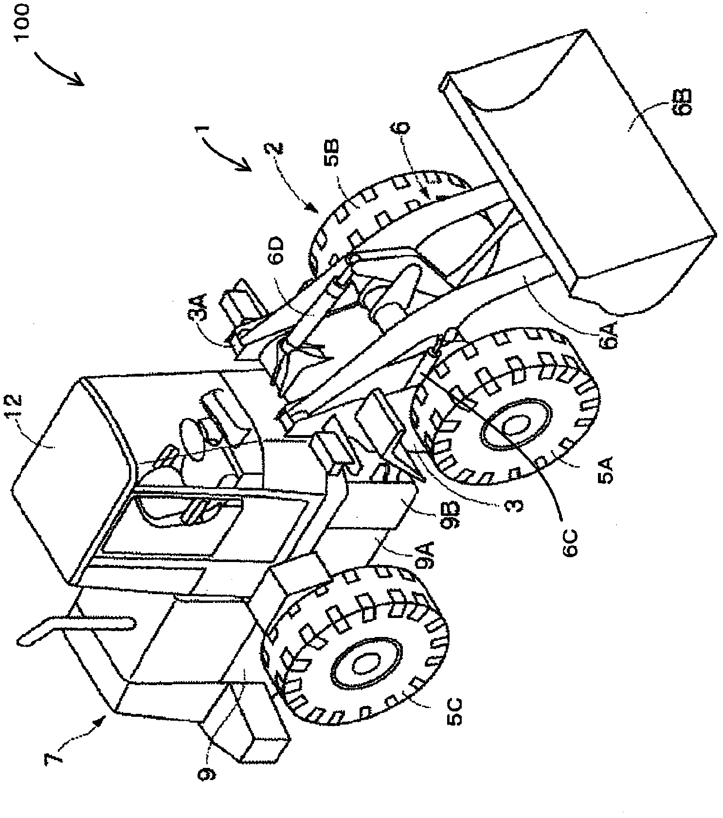
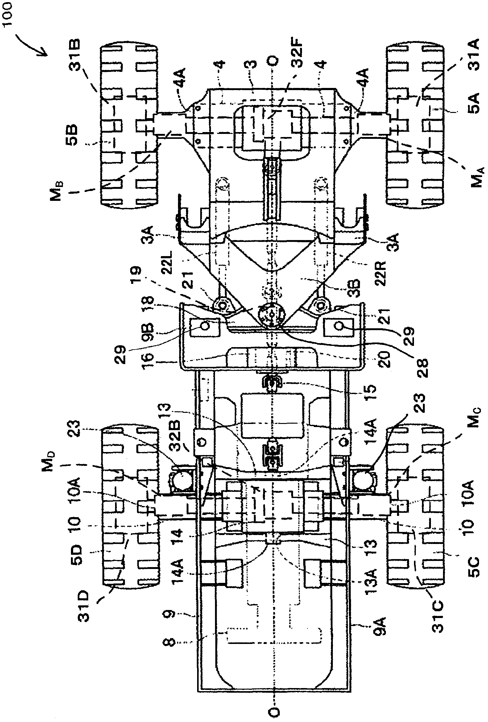
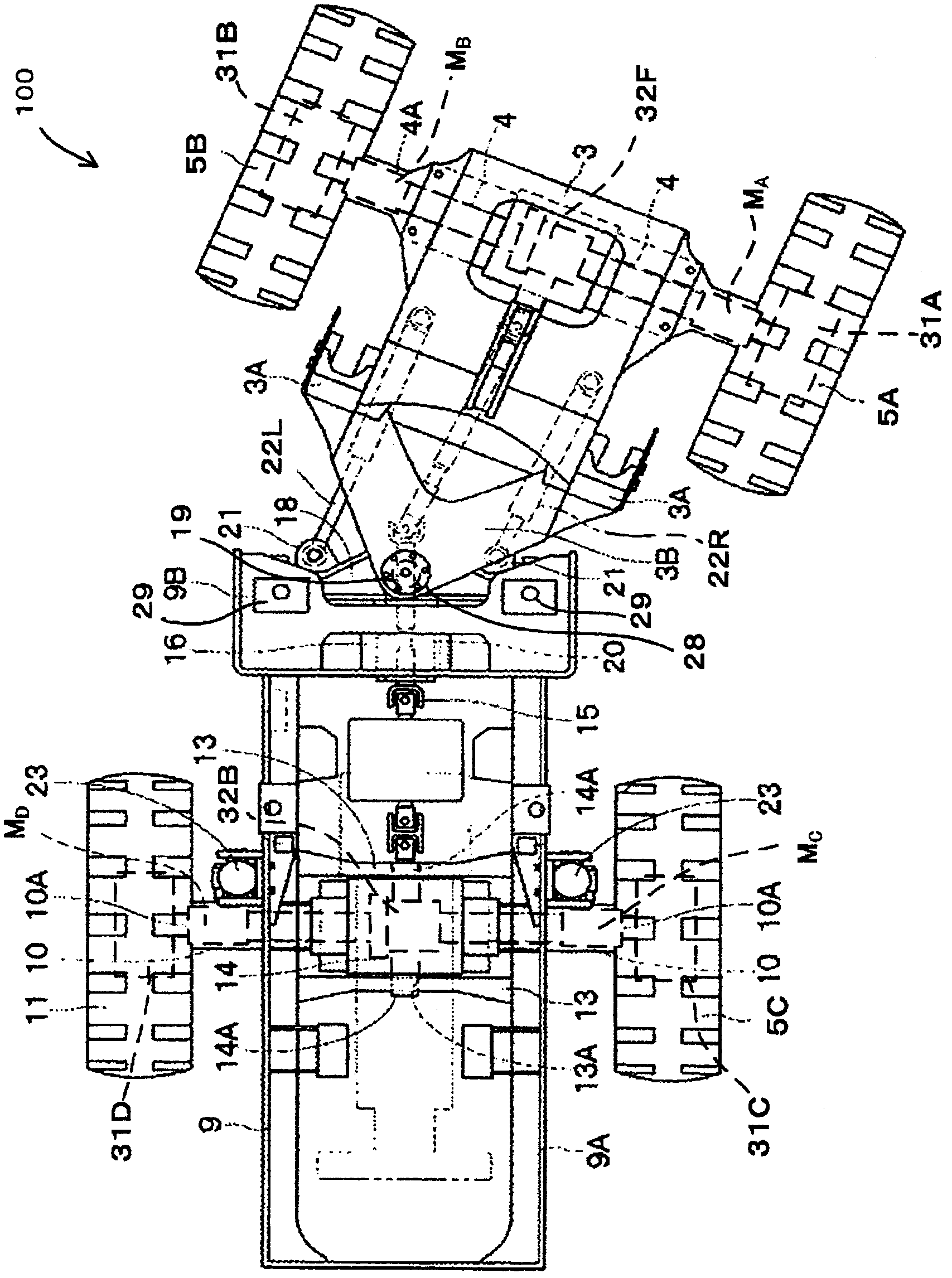
[0027] figure 1 It is a three-dimensional view of the appearance of a hybrid wheel loader, figure 2 yes figure 1 A top view of the hybrid wheel loader shown, image 3 yes figure 2 A top view of the wheel loader shown in its flexed state, Figure 4 yes figure 1 Side view of the hybrid wheel loader shown. But when Figure 2 ~ Figure 4 in, omitted figure 1 Illustration of work equipment (buckets) shown.

[0028] as described below, Figure 1 ~ Figure 4 The illustrated hybrid wheel loader 100 is a work vehicle having an articulated body 1 in which a front body 2 and a rear body 7 are flexibly connected by a joint frame 18 .

[0029] The front body 2 is arranged on the front side of the hybrid wheel loader 100, and includes: a front frame 3 formed in a substantially box shape; a front axle 4 provide...


PUM


Abstract

A wheel loader is provided with: a vehicle body having a front frame and a rear frame which are connected at a connection section in a steerable manner; at least a pair of front wheels mounted to the axle of the front frame and at least a pair of rear wheels mounted to the axle of the rear frame, the pair of front wheels and the pair of rear wheels being located at positions sandwiching the connection section; a pair of electric motors for front wheels, adapted to drive the pair of front wheels; a pair of electric motors for rear wheels, adapted to drive the pair of rear wheels; a direction conversion control unit which, in order that the front frame and the rear frame are rotated in the opposite directions about the connection section during steering operation, bends the vehicle body by driving the pair of electric motors for front wheels and the pair of electric motors for rear wheels so that the relative magnitudes between the speed of the inner wheels and the speed of the outer wheels are opposite and so that the speeds have a difference corresponding to the steered angle; and a turning and traveling control unit which, when it is determined that the steering operation is completed, drives the pair of electric motors for front wheels and the pair of electric motors for rear wheels so that a speed difference of the electric motor for the front wheel on the outer side and a speed difference of the electric motor for the front wheel on the inner side have speed differences for the inner and outer wheels, the speed differences corresponding to the steered angle, and so that a speed difference of the electric motor for the rear wheel on the outer side and a speed difference of the electric motor for the rear wheel on the inner side have speed differences for the inner and outer wheels, the speed differences corresponding to the steered angle.

Description

technical field [0001] The present invention relates to wheel loaders. Background technique [0002] The articulated wheel loader in which the front frame and the rear frame are bent with a connecting shaft as a rotation axis has a pair of left and right front wheels and a pair of left and right rear wheels at the front and rear of the connecting shaft. The left and right front wheels and the left and right rear wheels are respectively connected via a differential via a wheel axle. The rotation of the drive shaft of the engine is transmitted to the propeller shaft through the torque converter and the transmission, and the rotation of the propeller shaft is transmitted to the front and rear wheels through the differential, thereby driving the vehicle. [0003] In addition, there is also known a wheel loader in which electric motors are attached to the axles of the respective wheels, and the respective wheels of the pair of front wheels and the respective wheels of the pair o...

Claims


Application Information

Patent Timeline
Patent Type & Authority Applications(China)
IPC IPC(8): B62D12/00B62D5/28B62D11/04
CPCB62D12/00B60L2260/28B60L2220/42B60L2220/46B60L15/2036B62D11/04B60L11/12B62D11/02B60L2200/40Y02T10/70Y02T10/648B62D11/003Y02T10/7077Y02T10/72B60L50/15Y02T10/64Y02T10/7072B62D5/28B60K17/34
Inventor 伊藤德孝菊地彻
Owner NIHON KENKI CO LTD
Why Eureka
Try Eureka