Pressure reducing and defoaming device for molten glass, molten glass manufacturing method, and glass product manufacturing method

A technology of molten glass and manufacturing method, applied in glass manufacturing equipment, manufacturing tools, glass furnace equipment, etc., can solve the problems of difficulty in degassing and lowering the temperature of molten glass, and achieve the effect of preventing temperature reduction and efficient degassing

Active Publication Date: 2015-07-15
ASAHI GLASS CO LTD
View PDF8 Cites 0 Cited by
  • Summary
  • Abstract
  • Description
  • Claims
  • Application Information

AI Technical Summary

Problems solved by technology

[0006] However, when the flows of the molten glass in the vacuum degassing tank, the riser, and the downcomer are made of refractory furnace materials, the molten glass in the melting tank is introduced into the vacuum degassing tank without being heated. The temperature of the molten glass in the pressure degassing tank decreases, making degassing difficult

Method used


Image

  • Pressure reducing and defoaming device for molten glass, molten glass manufacturing method, and glass product manufacturing method
  • Pressure reducing and defoaming device for molten glass, molten glass manufacturing method, and glass product manufacturing method
  • Pressure reducing and defoaming device for molten glass, molten glass manufacturing method, and glass product manufacturing method

Examples


Embodiment Construction

[0033] Hereinafter, the vacuum degassing apparatus of the molten glass of this invention is demonstrated in detail based on embodiment shown in drawing.

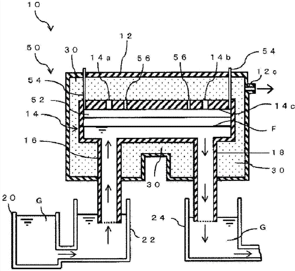
[0034] figure 1 It is a schematic side sectional view of the vacuum degassing apparatus (henceforth the vacuum degassing apparatus of this invention) of the molten glass concerning embodiment of this invention.

[0035] figure 1 The shown vacuum degassing device 10 has a vacuum housing 12 whose interior can be kept in a reduced pressure state. The decompression housing 12 is made of metal, and is provided with a suction port 12c for decompressing the inside by evacuation.

[0036] A vacuum degassing tank 14 is accommodated in the decompression housing 12 . Suction holes 14a, 14b communicating with the decompression housing 12 are provided on the upper portion of the degassing degassing tank 14 . By evacuating the decompression housing 12 from the suction port 12c using a vacuum pump (not shown), the inside of the degassi...


PUM

PropertyMeasurementUnit
sizeaaaaaaaaaa
thicknessaaaaaaaaaa

Abstract

Provided are: a pressure reducing and defoaming device for molten glass, capable of, while preventing a reduction in the temperature of molten glass, efficiently removing foams in the molten glass contained within a pressure reducing and defoaming tank; a molten glass manufacturing method utilizing the device; and a glass product manufacturing method. A pressure reducing and defoaming device for molten glass comprises: a pressure reducing housing, the inside of which is evacuated and reduced in pressure; a pressure reducing and defoaming tank provided within the pressure reducing housing and performing the pressure reduction and defoaming of molten glass; an ascending pipe provided so as to communicate with the pressure reducing and defoaming tank and sucking and raising the molten glass, which has not undergone the pressure reduction and defoaming, to introduce the molten glass into the pressure reducing and defoaming tank; and a descending pipe provided so as to communicate with the pressure reducing and defoaming tank and lowering and delivering the molten glass, which has undergone the pressure reduction and defoaming, from the pressure reducing and defoaming tank. An electric heating device is provided at a position above the surface of the molten glass located within the pressure reducing and defoaming tank, and below the lower surface of the upper wall of the pressure reducing and defoaming tank.

Description

technical field [0001] The present invention relates to a vacuum defoaming device for molten glass, a method for producing molten glass using the device, and a method for producing glass products. Background technique [0002] Conventionally, in order to improve the quality of glass products obtained by molding, before molding molten glass melted in a melting tank by a molding device, a clarification step is performed to remove air bubbles in the molten glass. As a method used in this clarification process, there exists a method of performing vacuum degassing on molten glass using a vacuum degassing apparatus. [0003] The vacuum defoaming device is used in the process of vacuum defoaming the molten glass in the melting tank and continuously supplying the molten glass to the next processing tank. The vacuum defoaming device has a vacuum casing whose interior is kept in a reduced pressure state by vacuuming. In the decompression housing, the degassing and degassing tank is ...

Claims


Application Information

Patent Timeline
Patent Type & Authority Patents(China)
IPC IPC(8): C03B5/225
CPCC03B5/2252
Inventor 浜岛和雄三好涉佐佐木道人增田健一
Owner ASAHI GLASS CO LTD
Why Eureka
Try Eureka