
Method for modeling mill end product in mining machinery

A kind of machinery and mill technology, applied in the direction of casting molding equipment, etc., can solve the problems of different core boxes, reduce production efficiency, increase the cost of patterns, etc., and achieve the effect of reducing production costs

Inactive Publication Date: 2013-02-13
NINGXIA KOCEL GRP CO LTD +1
View PDF4 Cites 7 Cited by
  • Summary
  • Abstract
  • Description
  • Claims
  • Application Information

AI Technical Summary

Problems solved by technology

The traditional molding scheme adopts the method of combining the outer shape and the core, and the method has the following defects: 1) Different shapes need to be prepared for the same series and different types of terminal products; 2) Different core boxes need to be prepared; 3) The traditional molding method, For the same series of different types of terminal products, the model cannot be used universally, and a new pattern is required, resulting in an increase in the cost of the pattern; 4) The pattern cannot be used universally, and different types of terminals need to be prepared before the molding process, which increases the production cycle and reduces production efficiency.
[0003] There is currently no way to overcome the above drawbacks

Method used


Image

  • Method for modeling mill end product in mining machinery
  • Method for modeling mill end product in mining machinery
  • Method for modeling mill end product in mining machinery

Examples


Embodiment Construction

[0024] A molding method for mill end products in mining machinery, characterized in that the method includes the following steps:

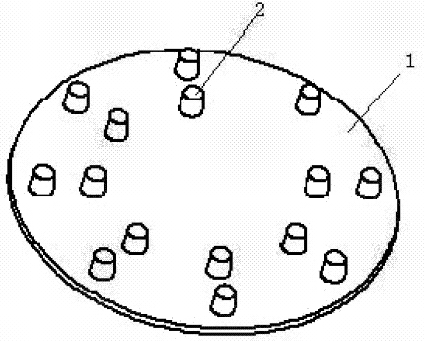
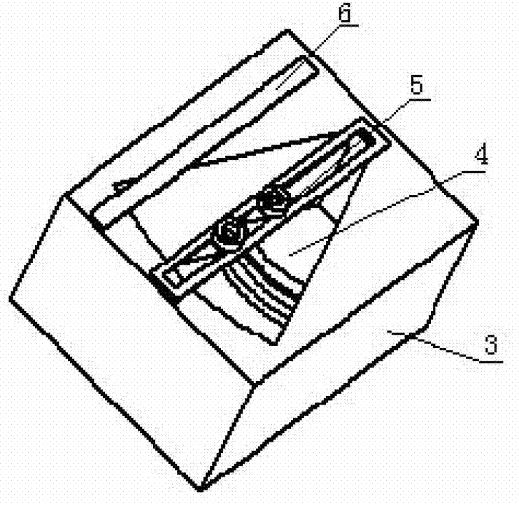
[0025] a. Make tire plate 1 first, such as figure 1 As shown: and on the upper surface of the tire plate 1, a sand core positioning platform 2 is provided, such as figure 2 Shown: prepare fan-shaped core box 3 then, be provided with the scraper plate 6 that scrapes sand core at the top of core box 3;

[0026] b. Place the tire plate 1 in the sand box, adjust the sand core positioning platform 2, and then flow molding sand into the sand box;

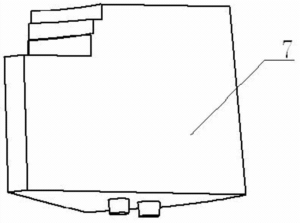
[0027] c. Put the core box 3 into the corresponding loose block 4, after checking that the position of the loose block 4 is accurate, fix the loose block 4, and prepare the quicksand as follows: image 3 The sand core 7;

[0028] d. scrape off the molding sand on the top of the core box 3 by the scraper 6;

[0029] E. prepare sand core positioning block 5 with quicksand, make sand core positioning block ...


PUM


Abstract

The invention relates to a product modeling method, and in particular relates to a method for modeling a mill end product in mining machinery. The method comprises the following steps of: manufacturing a tire plate, manufacturing a fan-shaped core box, and arranging a sand scraping plate for scraping a sand core on the upper part of the core box; arranging the tire plate in the sand box, and allowing molding sand to flow in the sand box; putting a corresponding die insert into the core box, fixing the die insert, and manufacturing the sand core through the molding sand; scraping the molding sand on the upper part of the core box through the sand scraping plate; manufacturing a sand core positioning block through molding sand; and arranging the sand core in a cavity formed in the tire plate according to a position where the sand core positioning block is matched with the positioning table, and forming a specific casting cavity. The method is unique; and according to the method for the tire plate and a variable core box, only a set of sample is required in the production process, the production requirements of a series of end products can be met, the production efficiency is improved, and the production cost is reduced.

Description

technical field [0001] The invention relates to a molding method of a product, in particular to a molding method of mill end products in mining machinery. Background technique [0002] The inlet and outlet end products of the mill are the main components of the mill, and the classification of the mill mainly depends on the size of the end products. The series of products at the inlet and outlet ends have the same structure, and the specific product model is determined by the change of diameter. The structure of terminal products is consistent, so the casting process of these products is basically the same, and the molding scheme is the same. The traditional molding scheme adopts the method of combining the outer shape and the core, and the method has the following defects: 1) Different shapes need to be prepared for the same series and different types of terminal products; 2) Different core boxes need to be prepared; 3) The traditional molding method, For the same series o...

Claims


Application Information

Patent Timeline
Patent Type & Authority Applications(China)
IPC IPC(8): B22C7/04B22C7/06
Inventor 杨建周催佰罗永建王新军杨学崇张婧付龙鲁云
Owner NINGXIA KOCEL GRP CO LTD
Learn More