
Drive device of polisher

A driving device and polishing machine technology, which can be applied in the direction of grinding driving device, grinding machine parts, grinding/polishing equipment, etc., can solve the problems of large motor load and easy wear and tear of belts, so as to prolong the service life and avoid loss. , The effect of reducing the motor load

Inactive Publication Date: 2013-02-13
CHA ENTERPRISE
View PDF5 Cites 0 Cited by
  • Summary
  • Abstract
  • Description
  • Claims
  • Application Information

AI Technical Summary

Problems solved by technology

[0004] In order to solve the shortcomings and limitations of the single belt driving mode of the drive device of the polishing machine in the prior art, the load of the motor is too large and the belt is easy to wear and tear. The configured multiple belts drive multiple driven wheels to rotate, which can effectively reduce the load on the motor and prolong the service life of the belt, which is very practical

Method used


Image

  • Drive device of polisher
  • Drive device of polisher
  • Drive device of polisher

Examples


Embodiment Construction

[0031] In order to understand the technical features and practical effects of the present invention in detail, and to implement them according to the contents of the description, the detailed description is as follows with the preferred embodiment shown in the accompanying drawings:

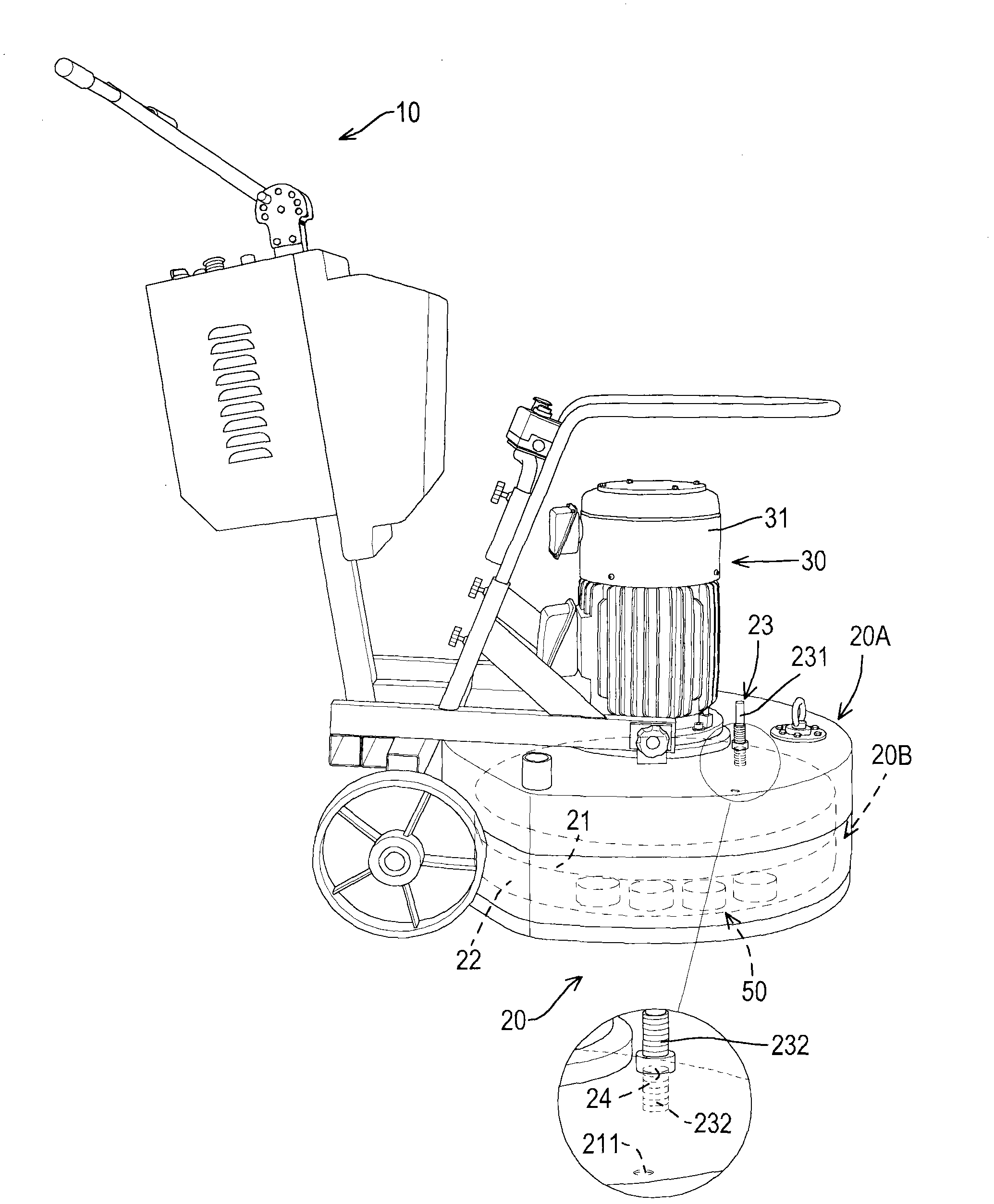
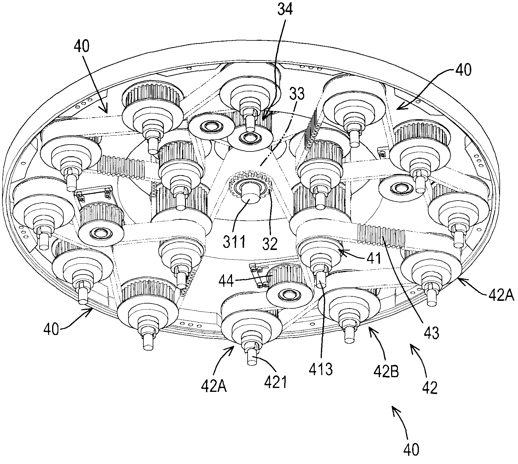
[0032] The first preferred embodiment of the driving device of a polishing machine provided by the present invention is combined with a machine body 10, such as figure 1 and figure 2 As shown, it includes: a housing 20, a driving unit 30, a plurality of transmission units 40 and a plurality of polishing units 50 and other components, wherein:

[0033] Such as figure 1 As shown, the body 10 is the prior art, and its detailed shape and structure will not be described in detail here.

[0034] Such as figure 1 , figure 2 and Figure 7 As shown, the housing 20 is fixed on the bottom of the body 10; preferably, the housing 20 includes an outer shell 20A and a rotatable inner shell 20B located in...


PUM


Abstract

The invention discloses a drive device of a polisher. The drive device comprises a shell, a drive unit arranged in the shell, a plurality of transmission units positioned in the shell and a plurality of polishing units, wherein the drive unit comprises a motor, a driving wheel connected with the motor and a drive rotation belt meshed with the driving wheel; each transmission unit comprises a transmission wheel meshed with the drive rotation belt, a plurality of driven wheels and a transmission belt; transmission belts of the transmission units are meshed with transmission wheels and a plurality of driven wheels of the corresponding transmission units; and a plurality of polishing units are respectively connected with a plurality of transmission units. By the drive device, a plurality of driven wheels are driven by the double-layer belts, so that load of the motor can be effectively reduced, the service lives of the belts are prolonged, and the drive device has extremely high practicality.

Description

technical field [0001] The invention relates to a component of a grinding machine, in particular to a driving device of a polishing machine. Background technique [0002] The driving device of the current prior art polishing machine includes a motor, a driving wheel sheathed on the mandrel of the motor, a plurality of driven wheels and a belt meshed with the driving wheel and the driven wheel, so when the mandrel of the motor rotates , the driving wheel uses the belt to drive multiple driven wheels to rotate, and then the polishing operation is carried out. [0003] However, the driving device of the polishing machine in the prior art uses a single belt to drive multiple driven wheels, resulting in an excessive load on the motor; in addition, the belt is easily worn out, so there is a need for improvement. Contents of the invention [0004] In order to solve the shortcomings and limitations of the single belt driving mode of the drive device of the polishing machine in th...

Claims


Application Information

Patent Timeline
Patent Type & Authority Applications(China)
IPC IPC(8): B24B47/00
Inventor 戴铭宗
Owner CHA ENTERPRISE
Learn More