Clamping device of blade type precision forging part

A clamping device and precision forging technology, which is applied in the direction of workpiece clamping device, measuring device, optical device, etc., can solve the problems of difficult detection of precision forging blade wool, white light scanning detection equipment cannot be compensated and corrected, and measurement accuracy is affected. Achieve the effects of high reliability and fast positioning and clamping, shorten product inspection cycle, and reduce product cost

Active Publication Date: 2013-02-13
AECC AVIATION POWER CO LTD
View PDF5 Cites 7 Cited by
  • Summary
  • Abstract
  • Description
  • Claims
  • Application Information

AI Technical Summary

Problems solved by technology

Since the jaws of the flat-mouth vise do not have the function of determining the unique position of the blade, each time a blade is inspected, the blade must be manually adjusted to an almost position that cannot be accurately measured. Due to the large batch of fine forging wool for blades, the labor intensity very big
Moreover, the white light scanning detection equipment belongs to non-contact measurement, and the measurement accuracy is greatly affected by the initial position of the parts. The same batch of blade wool is random due to the manual adjustment of the initial position deviation of the parts, which increases the interference factor. The white light scanning detection equipment itself cannot compensate and correct this. The initial position error, so the randomness of the initial position deviation of the parts affects the judgment of the inspection conclusion, resulting in poor consistency of the inspection conclusions of the same batch of blade wool, and the quality of the blade inspection is unstable
In short, the existing detection clamping scheme is time-consuming and laborious to operate, the detection efficiency is extremely low, and it is easy to cause false detection
The above problems have brought great difficulties to the detection of fine forging blade blanks. It is necessary to design a special clamping device for such blade parts with complex geometric shapes that are difficult to locate to solve the above problems.

Method used


Image

  • Clamping device of blade type precision forging part
  • Clamping device of blade type precision forging part
  • Clamping device of blade type precision forging part

Examples


Embodiment Construction

[0022] Describe the present invention below in conjunction with specific embodiment:

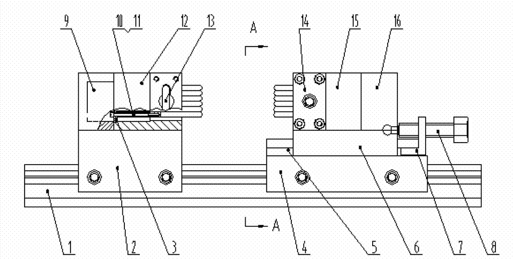
[0023] The clamping device for blade precision forging parts in this embodiment is based on the idea of ​​dot-matrix positioning needle field, and consists of a guide rail base 1, a fixed clamping end assembly and a moving clamping end assembly.

[0024] The fixed clamping end assembly includes a fixed end slider 2, a fixed end cap 9, a fixed end body 12 and several positioning claws.

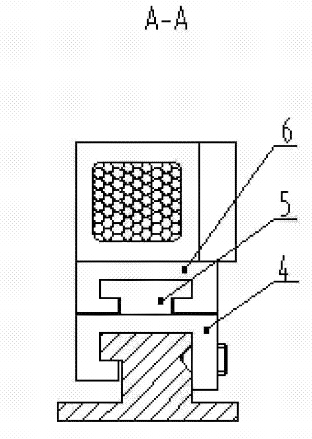
[0025] The slider at the fixed end cooperates with the base of the guide rail and can slide freely on the base of the guide rail. There are two threaded holes in the side wall of the fixed end slider, which are used to lock the fixed end slider to the rail base. There are 2 groups of screw holes on the upper surface of the fixed end slider, one group is connected with the fixed end cap 9, and the other group is connected with the fixed end body 12, so that it is connected with the fixed end slider 2 as a who...


PUM


Abstract

The invention provides a clamping device of a blade type precision forging part. The device comprises a guide rail base, a fixing clamping end component and a mobile clamping end component, wherein the fixing clamping end component comprises a fixing end sliding block, a fixing end cover, a fixing end body and a plurality of positioning claws, and the mobile clamping end component comprises a main mobile end sliding block, a mobile end pushing component, a mobile end cover, a mobile end body and a plurality of positioning claws. According to the device, a plurality of positioning claws with pressure springs forms needle field type flexible clamping, when a complex part is clamped, a positioning claw at the position of the part moves towards a groove of the fixing end cover or the mobile end cover along a through-hole on a gasket, positioning claws at other positions can be formed along the geometrical shape of the outline of a part, a fixing end kidney-shaped pressing plate and a mobile end kidney-shaped pressing plate are fixed tightly through a fixing end kidney-shaped pressing plate pressing device and a mobile end kidney-shaped pressing plate pressing device, and the kidney-shaped pressing plates at two ends press the positioning claws on two ends respectively, so that the outline of the part can be maintained, and the part can be clamped.

Description

technical field [0001] The invention relates to the mechanical field of mechanical clamping devices, in particular to a clamping device for blade precision forging parts. Background technique [0002] Before the inspection of fine forged blade wool, it is necessary to allow the same batch of blades to have a definite position to be inspected relative to the white light scanning inspection equipment, so that the inspection conclusions of the same batch of wool have similar consistency. In the past, small flat-mouth vises were used to clamp parts for positioning. Since the jaws of the flat-mouth vise do not have the function of determining the unique position of the blade, each time a blade is inspected, the blade must be manually adjusted to an almost position that cannot be accurately measured. Due to the large batch of fine forging wool for blades, the labor intensity very big. Moreover, the white light scanning detection equipment belongs to non-contact measurement, and ...

Claims


Application Information

Patent Timeline
Patent Type & Authority Applications(China)
IPC IPC(8): B25B11/00G01B11/24G01B11/00
Inventor 王素娟陈琦吴芳王荣吕学春
Owner AECC AVIATION POWER CO LTD
Why Eureka
Try Eureka