Wire falling array type inflatable unfolding wing

A technology of inflatable deployment and wings, applied in wings, aircraft parts, transportation and packaging, etc., can solve the problems of low connection efficiency, heavy weight, complex system, etc., and achieve the effect of high connection efficiency, light weight and simple process

Active Publication Date: 2013-02-13
HARBIN INST OF TECH
View PDF4 Cites 20 Cited by
  • Summary
  • Abstract
  • Description
  • Claims
  • Application Information

AI Technical Summary

Problems solved by technology

[0003] The purpose of the present invention is to solve the problems of low connection efficiency, heavy weight and complicate...

Method used


Image

  • Wire falling array type inflatable unfolding wing
  • Wire falling array type inflatable unfolding wing
  • Wire falling array type inflatable unfolding wing

Examples


specific Embodiment approach 1

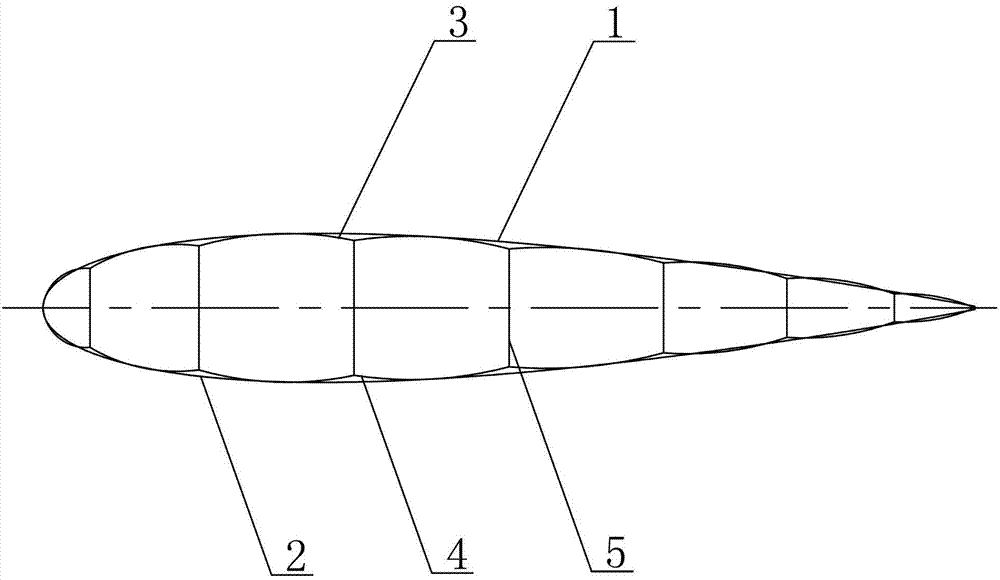
[0011] Specific implementation mode one: combine figure 1 Describe this embodiment, a doffing array type inflatable expandable wing of this embodiment includes an upper skin 1 of an inflatable wing and a lower skin 2 of an inflatable wing, an upper skin 1 of an air wing and a lower skin 2 of an inflatable wing The inflatable and expandable wings also include an upper connecting piece 3, a lower connecting piece 4 and a plurality of suspension locks 5, and the upper connecting piece 3 and the lower connecting piece 4 are respectively fixed by butt joint heat sealing. On the inner walls of the upper skin 1 of the airfoil and the lower skin 2 of the airfoil, a plurality of suspension locks 5 are vertically connected between the upper connecting piece 3 and the lower connecting piece 4 .

[0012] In this embodiment, a suspension cable structure is introduced into the cross section inside the inflatable wing, and the suspension cable and the upper and lower skins are connected thro...

specific Embodiment approach 2

[0015] Specific implementation mode two: combination figure 1 Describe this embodiment, the materials of the upper skin 1 and the upper connecting piece 3 of the inflated wing after butt joint heat sealing in this embodiment are PA, TIE, PE, TIE, PA, TIE and PE seven layers in total. Squeeze film. With such setting, the material has strong air barrier performance, good heat sealing performance, strong mechanical performance and anti-oxidation. Other compositions and connections are the same as in the first embodiment.

specific Embodiment approach 3

[0016] Specific implementation mode three: combination figure 1 This embodiment will be described. The seven-layer co-extruded film of this embodiment has a thickness of 70 μm and a modulus of 550 MPa. Such setting facilitates single-sided heat sealing. Other compositions and connections are the same as those in Embodiment 1 or Embodiment 2.


PUM

PropertyMeasurementUnit
Thicknessaaaaaaaaaa
Modulusaaaaaaaaaa
Modulusaaaaaaaaaa

Abstract

A wire falling array type inflatable unfolding wing relates to an inflatable unfolding wing. The invention solves the problems that most conventional inflatable wings adopt a brace type, a multi-tube type or a suspended net type, and the internal structures of the conventional inflatable wings are low in connecting efficiency, heavy in weight and complex in system. An upper skin (1) and a lower skin (2) of an inflatable wing are buckled with each other and connected hermetically; an upper connecting plate (3) and a lower connecting plate (4) are fixedly mounted on the inner walls of the upper skin (1) and the lower skin (2) of the inflatable wing through a butt-joint heat-seal manner respectively; and a plurality of suspended zip-fasteners (5) are vertically connected between the upper connecting plate (3) and the lower connecting plate (4). A wire falling array type scheme that a vertical suspended stay rope is introduced between the upper skin and the lower skin is adopted, so that under the premise that requirements on the pressure maintaining control structure are satisfied, the process is simple, the connecting efficiency is high, the used material is less, and the weight is lightest. The wire falling array type inflatable unfolding wing is especially suitable for unmanned aerial vehicles with inflatable wings.

Description

technical field [0001] The invention relates to an inflatable and expandable airfoil, in particular to an inflatable and expandable airfoil of doffing array type. Background technique [0002] With the development of near-space vehicles, its high flight altitude, long cruising time, and foldable features have attracted more attention, and these characteristics also determine that near-space vehicles are developing towards lightweight and large-scale, so people began to Extensive research into foldable and deployable ultra-lightweight near-space vehicles. As a kind of near-space vehicle, the air wing UAV is the main structural component, and the foldable and unfoldable ultra-light inflatable wing structure represents the forward direction of the inflatable wing UAV. Most of the existing inflatable wings are bracing type, multi-tube type and hanging net type, and their internal structures all have the problems of low connection efficiency, heavy weight and complex system. C...

Claims


Application Information

Patent Timeline
IPC IPC(8): B64C3/30
Inventor 王长国刘远鹏夏震猛龚芃谭惠丰
Owner HARBIN INST OF TECH
Why Eureka
Try Eureka