End-bend blade for improving working stability of gas compressor

A technology of stability and compressor, which is applied to components, mechanical equipment, machines/engines, etc. of pumping devices used for elastic fluids, and can solve problems such as poor working stability of compressors, so as to improve working stability and inhibit flow separation effect

Inactive Publication Date: 2013-02-13
HARBIN TURBINE
View PDF3 Cites 7 Cited by
  • Summary
  • Abstract
  • Description
  • Claims
  • Application Information

AI Technical Summary

Problems solved by technology

[0003] The purpose of the present invention is to solve the problem that the guide vane of the existing compressor increases with the load, and the positive angle of attack near the end wall gradually increases

Method used


Image

  • End-bend blade for improving working stability of gas compressor
  • End-bend blade for improving working stability of gas compressor
  • End-bend blade for improving working stability of gas compressor

Examples


specific Embodiment approach 1

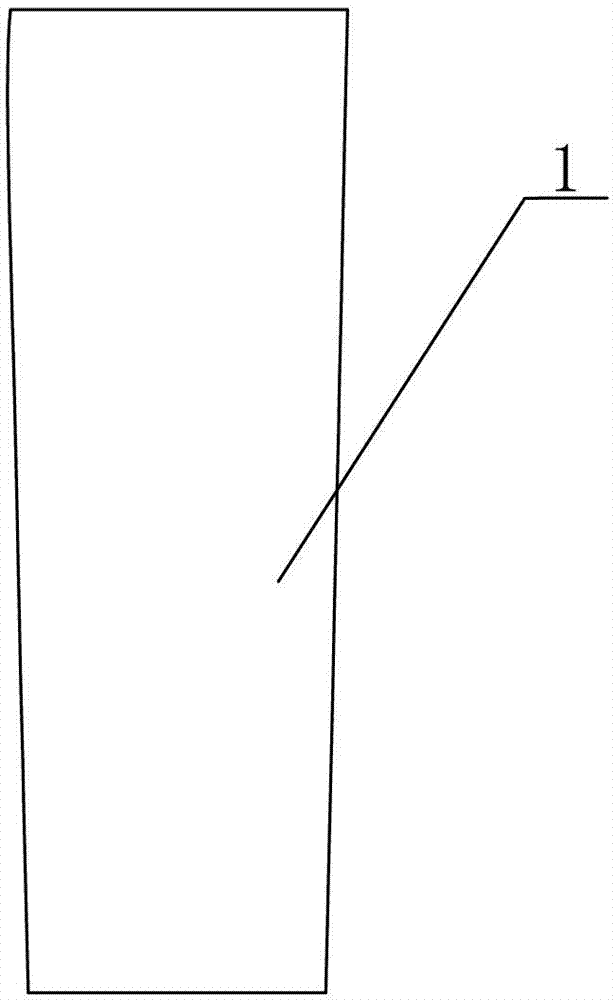
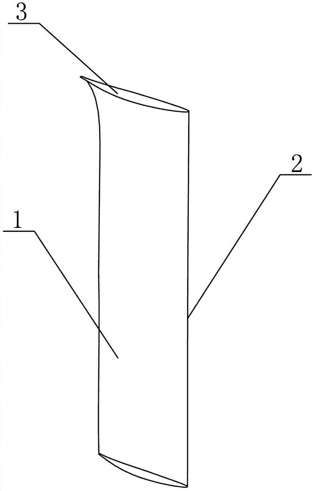
[0007] Specific implementation mode one: combine Figure 1-Figure 3 Describe this embodiment. An end-curved blade used to improve the working stability of a compressor in this embodiment includes a guide vane 1. The upper part of the guide vane 1 is an end-curved area 3, and the end-curved area 3 follows the track of the stacking line 2. Carry out end bending, the end bending height of the end bending area 3 is 7% of the overall height of the guide vane 1, in the end bending height area, the inlet geometric angle of the guide vane 1 increases linearly along the blade height by 0°-10°, the guide vane The end-curved vane at the upper end of 1 is offset from the middle of guide vane 1 to the side of the suction surface by 0mm-7.53mm.

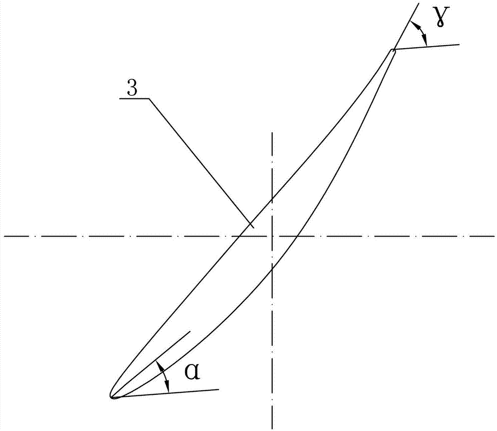
[0008] The outlet geometric angle of this embodiment is γ, γ=57.65°, the chord length is 51.94mm, and the maximum thickness is 6.98mm.

specific Embodiment approach 2

[0009] Specific implementation mode two: combination image 3 To illustrate this embodiment, the end curvature height of the upper part of the guide vane 1 in this embodiment is 11.94 mm, the inlet geometric angle of the guide vane 1 is α, α=45.3°, and the end curve shape of the upper end of the guide vane 1 is relative to the guide vane 1 The offset of the middle part to the side of the suction side is 7.53mm. With this setting, the pressure ratio of the single-stage compressor is increased by 1%, and the isentropic efficiency of the single-stage compressor is increased by 3% compared with that before the modification. It can also effectively suppress the flow separation in the end zone, making the inflow and outflow of the airflow more efficient. Fit the blade curve of the blade, match the angle of the mainstream area of ​​the compressor, and improve the working stability of the compressor. Other components and connections are the same as those in the first embodiment.


PUM

PropertyMeasurementUnit
Chord lengthaaaaaaaaaa
Maximum thicknessaaaaaaaaaa

Abstract

The invention discloses an end-bend blade for improving the working stability of a gas compressor, which relates to the end-bend blade and solves the problems that a guide blade of the traditional gas compressor is enlarged with the load, a positive angle of attack at the position close to the end wall is gradually increased, thus the gas compressor enters into a stall situation in advance, and the working stability of the gas compressor is poor. The end-bend blade comprises a guide blade (1), wherein the upper part of the guide blade (1) is an end-bend area (3), the end-bend area (3) is subjected to end bending along a track of a stacking line (2), the end-bend height of the end-bend area (3) is 7% of the total height of the guide blade (1), an inlet geometric angle of the guide blade (1) is linearly increased by 0-10 degrees along the blade height in an end-bend height area, and an end-bend blade profile at the upper end of the guide blade (1)shifts 0-7.53 mm towards one side of a suction surface relative to the middle part of the guide blade (1). According to the end-bend blade disclosed by the invention, the inflow and the outflow of airflow can be more in fit with a blade profile curve of the blade and can be matched with an angle of a main flow area of the gas compressor, and the working stability of the gas compressor can be increased. The end-bend blade disclosed by the invention is used in the gas compressor.

Description

technical field [0001] The invention relates to an end curved blade, in particular to an end curved blade for improving the working stability of a compressor. Background technique [0002] In the current large-flow multi-stage axial flow compressor, due to the cumulative effect of the boundary layer on the upper and lower end walls of the guide vanes at the front stages, the boundary layer at the inlet end area of ​​the four-stage guide vanes at the rear is thicker, accounting for a larger range of blade height. , flow separation is prone to occur, resulting in the deterioration of the flow condition in the end zone, and the rapid decrease of the axial velocity in the end zone, causing the airflow direction near the end wall to deviate from the design value, resulting in a positive angle of attack. As the load increases, the near end wall The positive angle of attack gradually increases, so that the compressor enters the stall condition early, and the working stability of th...

Claims


Application Information

Patent Timeline
IPC IPC(8): F04D29/38
Inventor 张秋鸿张宏涛冯永志王松涛张成义杜鑫张春梅赵俊明慕粉娟马波黄伟成
Owner HARBIN TURBINE
Why Eureka
Try Eureka