Pipeline oil heater

A heater and oil technology, used in fluid pressure actuation devices, fluid pressure actuation system components, mechanical equipment, etc. problem, to achieve the effect of high heating efficiency, fast heating speed and long service life

Inactive Publication Date: 2013-02-13
XIAN QINGAN AERONAUTICAL TESTING EQUIP
View PDF10 Cites 4 Cited by
  • Summary
  • Abstract
  • Description
  • Claims
  • Application Information

AI Technical Summary

Problems solved by technology

[0002] There are two types of oil heaters (or devices) used in traditional hydraulic pipelines: one is that the electric heater is directly placed in the pipeline oil for heating, and the other is the heating method that uses hot air, hot oil, belt or Coated electric heaters and other heat sources heat the outer wall of the pipeline to realize the heating of the oil in the pipe; the former is easy to carbonize and degrade the oil and pollute the oil because the surface of the high-temperature electric heater is in direct contact with the oil, reducing the oil and The service life of other components of the hydraulic system; although the latter method avoids the shortcomings of the former method, it needs to be equipped with a heating air or oil device, which has the disadvantages of large volume, low efficiency, and large thermal inertia. Hot air and belt heating There are safety hazards such as flammability

Method used


Image

  • Pipeline oil heater
  • Pipeline oil heater

Examples


Embodiment Construction

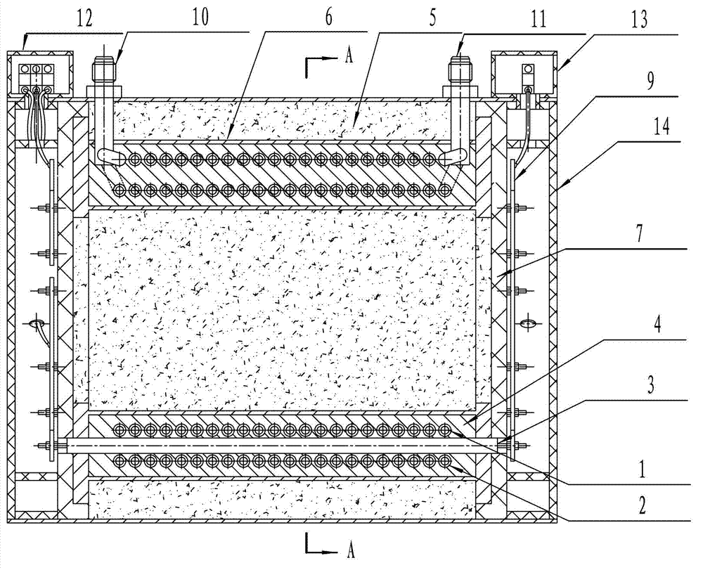
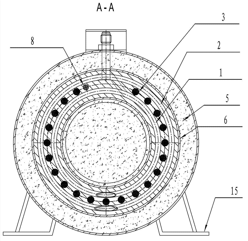
[0024] Pipeline oil heater, including hydraulic inner coil 1, hydraulic outer coil 2 and multiple electric heating tubes 3 arranged in parallel, the two ends of the hydraulic inner coil 1 and hydraulic outer coil 2 adopt oil inlet pipe joints 10 and the oil return pipe joint 11 are welded in parallel, and the hydraulic inner coil 1 and the hydraulic outer coil 2 welded in parallel are fixedly installed in the sandwich shell 6, and the aluminum alloy heating body 4 which constitutes an integral part is wrapped by aluminum alloy casting; Both the inner cavity and the outer part of the heating body are filled with thermal insulation material 5 .

[0025] A plurality of electric heating tubes 3 are distributed in the aluminum alloy cylindrical layer formed between the hydraulic inner coil 1 and the hydraulic outer coil 2 , and the connecting terminals of the electric heating tubes 3 are arranged at both ends of the aluminum alloy cylindrical layer. In addition, a temperature senso...


PUM


Abstract

The invention provides a pipeline oil heater. By the pipeline oil heater, oil is continuously heated under continuous flow conditions, and the operation is safe, reliable and high-efficiency. The pipeline oil heater comprises hydraulic inner coils and hydraulic outer coils which are parallel to each other, and a plurality of electric heating tubes, wherein two ends of the hydraulic inner coils and hydraulic outer coils are parallelly welded by employing oil inlet pipe joints and oil return pipe joints and are coated through aluminum alloy casting to form an integrated aluminum alloy heating body; a temperature sensor is arranged in the aluminum alloy heating body; the electric heating tubes are distributed in an aluminum alloy cylindrical layer formed between the hydraulic inner coils and hydraulic outer coils; wiring terminals of the electric heating tubes are arranged at two ends of the aluminum alloy cylindrical layer; and thermal insulation materials are filled in an inner cavity of the aluminum alloy heating body and outside the aluminum alloy heating body. The pipeline oil heater is high in heating speed and high in heating efficiency, an oil carbonization phenomenon is avoided, and the oil is long in service life, safe and reliable and working pressure is high.

Description

technical field [0001] The invention relates to a heater, in particular to an oil heater used in a hydraulic pipeline. Background technique [0002] There are two types of oil heaters (or devices) used in traditional hydraulic pipelines: one is that the electric heater is directly placed in the pipeline oil for heating, and the other is the heating method that uses hot air, hot oil, belt or Coated electric heaters and other heat sources heat the outer wall of the pipeline to realize the heating of the oil in the pipe; the former is easy to carbonize and degrade the oil and pollute the oil because the surface of the high-temperature electric heater is in direct contact with the oil, reducing the oil and The service life of other components of the hydraulic system; although the latter method avoids the shortcomings of the former method, it needs to be equipped with a heating air or oil device, which has the disadvantages of large volume, low efficiency, and large thermal inert...

Claims


Application Information

Patent Timeline
IPC IPC(8): F15B21/04
Inventor 潘耀勤易宗琴张镐京
Owner XIAN QINGAN AERONAUTICAL TESTING EQUIP
Why Eureka
Try Eureka