
Buffer air chamber structure of vehicle compressed natural gas (CNG) pressure reducing valve

A natural gas and pressure reducing valve technology, applied in the valve operation/release device, valve details, valve device and other directions, can solve the problems of high technical requirements, leakage, inability to reuse, etc., to achieve sufficient forward momentum, increased flow, The effect of easy disassembly

Active Publication Date: 2013-02-13
FUJIAN HUALONG CARBURETOR
View PDF6 Cites 8 Cited by
  • Summary
  • Abstract
  • Description
  • Claims
  • Application Information

AI Technical Summary

Problems solved by technology

[0006] The disadvantages of this kind of buffer air chamber are: 1. The riveting and fixing process of the isolation ring disc is complicated, the technical requirements are high, and there is a hidden danger of leakage at the same time
2. During maintenance, the isolation ring disk cannot be disassembled, and it cannot be reused after disassembly
Another kind of air outlet buffer air channel structure vertical confluence exists converging resistance

Method used


Image

  • Buffer air chamber structure of vehicle compressed natural gas (CNG) pressure reducing valve
  • Buffer air chamber structure of vehicle compressed natural gas (CNG) pressure reducing valve
  • Buffer air chamber structure of vehicle compressed natural gas (CNG) pressure reducing valve

Examples


Embodiment Construction

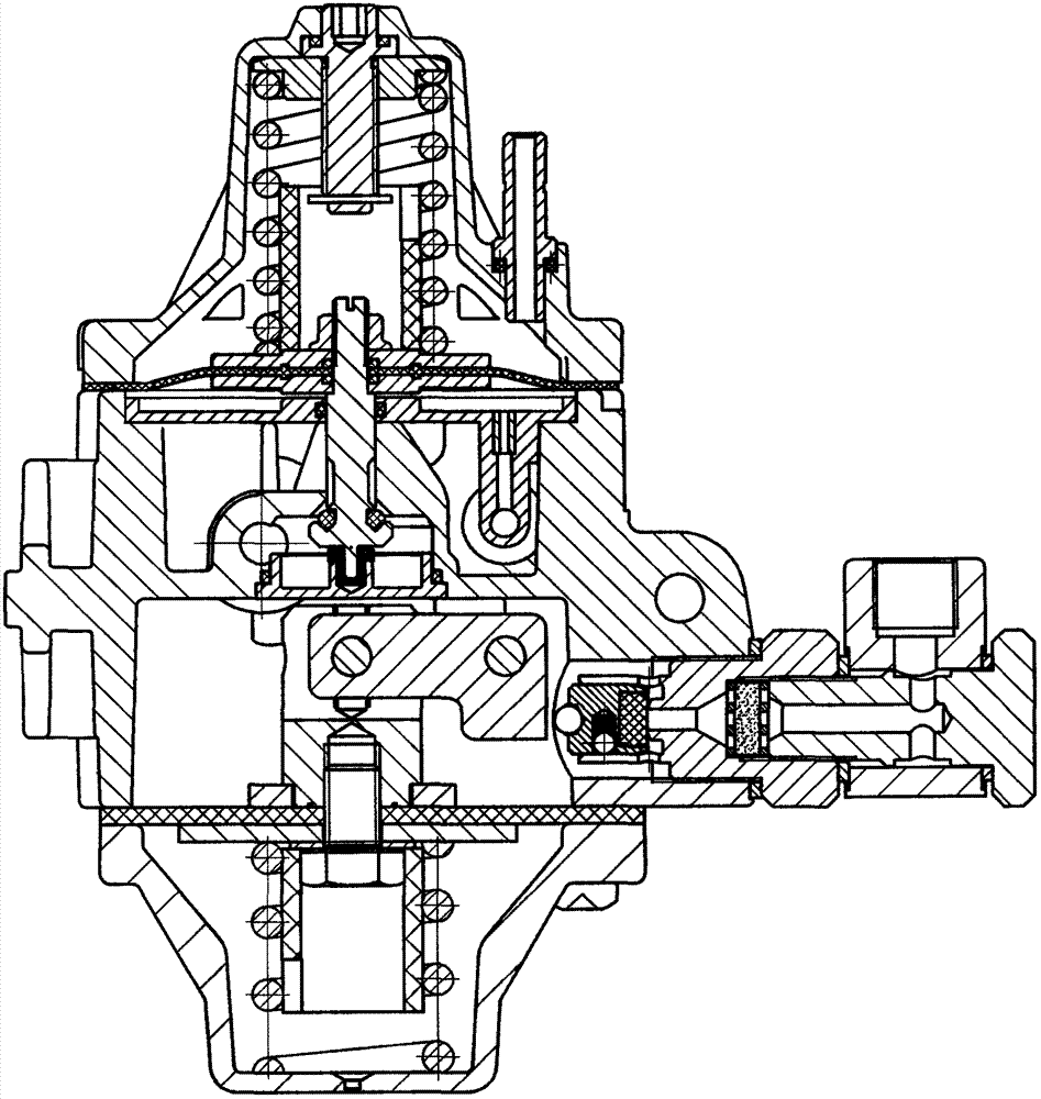
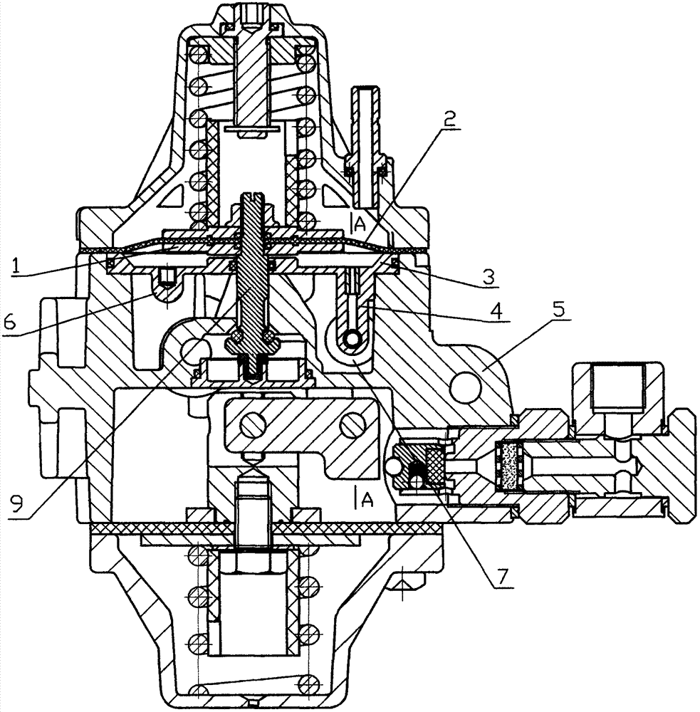
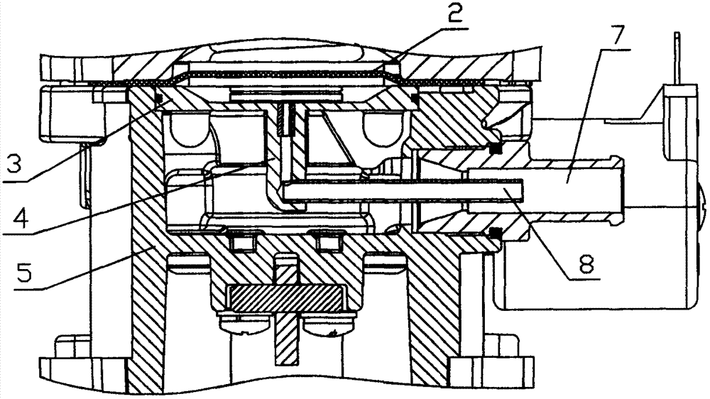
[0013] The present invention includes: isolating the ring disc 3, the upper elastic diaphragm 2, the lower spring gasket 1, the top membrane rod 9, the annular step groove and the air outlet 7 of the middle housing 5, and is characterized in that: the isolation ring disc 3 and the The annular step groove of the middle shell 5 is of the same height, and the outer circle of the isolation ring disc 3 is provided with a central circumferential groove, and a rubber sealing ring is fitted in the circumferential groove, and the outer circle of the isolation ring disc 3 is dynamically fit and fitted on the In the annular step groove of the middle shell 5, a ring groove is arranged on the upper surface of the isolation ring disc 3, and the top film rod 9 elastically fits through the central hole of the isolation ring disc 3 to fit a fixed rubber sealing ring; the isolation ring disc 3. The inner circle of the L-shaped orifice tube 4 extended in one piece is fixedly fitted with a horizon...


PUM


Abstract

The invention provides a buffer air chamber structure of a vehicle compressed natural gas (CNG) pressure reducing valve and relates to a valve structure. The buffer air chamber structure of the vehicle CNG pressure reducing valve comprises an isolation annular plate, an upper elastic membrane, a lower spring washer, a membrane ejection rod, an annular step groove of a central casing and an air outlet. The buffer air chamber structure is characterized in that the isolation annular plate and the annular step groove of the central casing are the same in height, a circumferential groove is arranged in the middle of an outer circle of the isolation annular plate, a rubber sealing ring is sleeved in the circumferential groove, the outer circle of the isolation annular plate is sleeved in the annular step groove of the central casing in movable fit mode, an annular groove is arranged on the upper surface of the isolation annular plate, the membrane ejection rod penetrates through the rubber sealing ring sleeved and fixed in a central hole of the isolation annular plate in elastic fit mode, a horizontal copper pipe is fixedly sleeved in a horizontal pipe of an L-shaped hole pipe extending from a connecting body of the isolation annular plate, the outer diameter of the horizontal pipe is less than the inner diameter of the air outlet, and the horizontal copper pipe extends into an inner circle of the air outlet. The buffer air chamber structure of the vehicle CNG pressure reducing valve has the advantage that the isolation annular plate and the circumferential groove are in movable fit so as to be convenient to disassemble, the horizontal copper pipe extends into the air outlet so as to enable an airflow column to form jet flow, and the buffer air chamber structure is slow in flow extension, sufficient in impulsion and rapid in forward flow velocity.

Description

Technical field: [0001] The invention relates to a valve structure, in particular to a buffer gas chamber structure of a natural gas CNG pressure reducing valve for vehicles. Background technique: [0002] As a gas fuel, CNG (compressed natural gas) mixes more evenly with air, burns more fully, and emits less harmful substances such as CO and HC; natural gas has no carbon deposit after combustion, which can reduce engine wear and maintenance costs; Natural gas engines are easy to refit, especially dual-fuel engines refitted with gasoline engines, which are widely used because of their high cost performance. Therefore, the current use of compressed natural gas (CNG) as fuel for new energy vehicles meets current environmental protection requirements. [0003] Gasification and decompression must be carried out in the pressure reducing valve before the cylinder compresses 20MPa natural gas CNG gas into the cylinder of the automobile engine for combustion. At present, the pressu...

Claims


Application Information

Patent Timeline
Patent Type & Authority Applications(China)
IPC IPC(8): F16K31/126
Inventor 雷祥雨郑节昭
Owner FUJIAN HUALONG CARBURETOR
Learn More