Method for positioning rotor rubbing sound emission source by applying time delay estimation

A technology of time delay estimation and rubbing sound, which is used in positioning, measuring devices, instruments, etc., can solve the problem of not considering signal attenuation, error, etc., to improve the accuracy of time delay estimation, improve performance, and reduce steady-state imbalance. amount of effect

Inactive Publication Date: 2014-04-16
SOUTHEAST UNIV
View PDF2 Cites 0 Cited by
  • Summary
  • Abstract
  • Description
  • Claims
  • Application Information

AI Technical Summary

Problems solved by technology

However, this algorithm only tracks the time-varying signal-to-noise ratio, and does not take into account the attenuation of the signal itself. It will cause a large error when directly applied to the positioning of the AE source.

Method used


Image

  • Method for positioning rotor rubbing sound emission source by applying time delay estimation
  • Method for positioning rotor rubbing sound emission source by applying time delay estimation
  • Method for positioning rotor rubbing sound emission source by applying time delay estimation

Examples


Embodiment Construction

[0031] The technical solution of the present invention will be further elaborated below in conjunction with the accompanying drawings and examples.

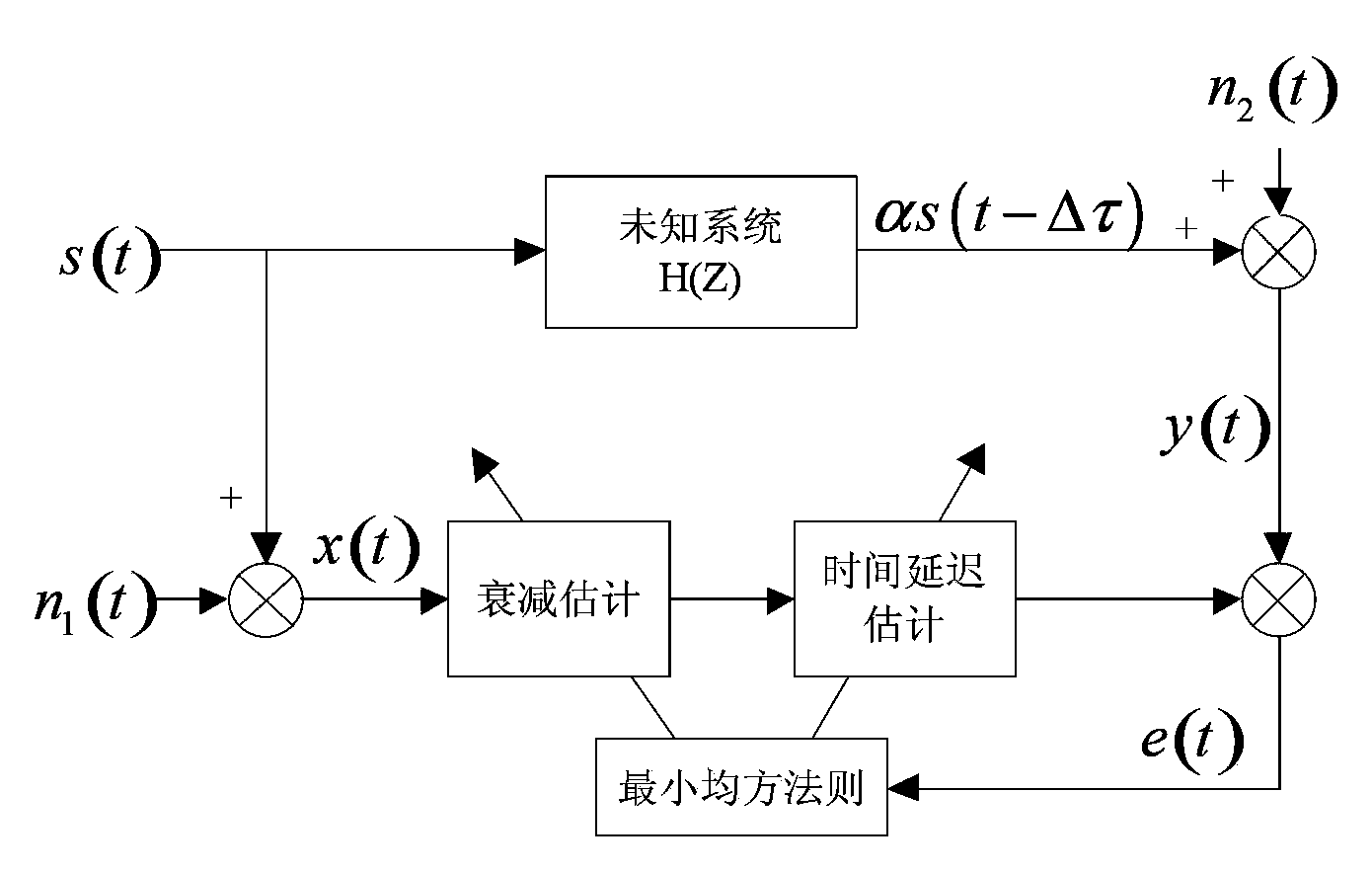
[0032] Such as figure 1 with figure 2 As shown, a method for locating the rotor rubbing acoustic emission source using time delay estimation of the present invention includes the following steps:

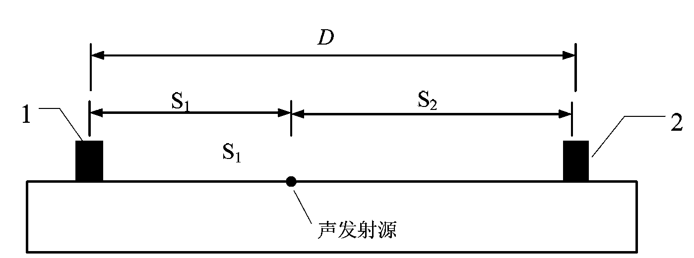
[0033] 10): Establish a one-dimensional linear positioning model: set two sensors, the first sensor 1 and the second sensor 2, on the rubbing waveguide plate of the rotor test bench, the rotor rubbing source is located between the two sensors, and the rotor rubbing The source and the two sensors are located on the same straight line. After the rotor rubs, an acoustic emission signal is generated, which is received by the two sensors. The acoustic emission signal is accompanied by attenuation and noise interference during propagation.

[0034] In step 10), the rotor rubbing acoustic emission signal is obtained by obtaining the rotor ...


PUM


Abstract

The invention discloses a method for positioning rotor rubbing sound emission source by applying time delay estimation, which comprises the following steps of: (10) building a one-dimensional linear positioning model; (20) setting a primary iteration value of attenuation coefficient estimation and a primary iteration value of time delay estimation; (30) calculating an estimation error between a real value and an estimation value; (40) calculating a next iterative step size according to the estimation error; (50) calculating iterated time delay estimation and attenuation coefficient estimation; (60) calculating a new estimation error; and (70) comparing relative error of the two estimation errors calculated in the step (30) and the step (60), measuring the position of the rubbing source according to delay time estimation if the relative error is smaller than a set value, or forwarding to the step (40) to continue iteration. According to the method, the problem of signal attenuation and strong noise interference during transmission of a rubbing sound emission signal of a rotor system is considered, and the rubbing fault source is accurately positioned by adding steps of attenuation estimation and changing the step size.

Description

technical field [0001] The invention relates to a method for locating a rotor rubbing acoustic emission source, in particular to a method for locating a rotor rubbing acoustic emission source by using time delay estimation. Background technique [0002] Rubbing of moving and static parts of rotating machinery is a common fault in operation. In particular, the current rotating machinery is developing towards large-scale, high-parameter, and high-efficiency development. The equipment structure is becoming more and more complex, and the dynamic and static gaps are getting smaller and smaller, which makes the rubbing problem of moving and static parts more and more prominent. Acoustic emission technology (Acoustic Emission, AE) is an effective method for diagnosing rubbing faults. It can not only judge the occurrence of rubbing, but also calculate the location of rubbing through positioning technology, which has important application value. Time Delay estimation (TDE) is a meth...

Claims


Application Information

Patent Timeline
Patent Type & Authority Patents(China)
IPC IPC(8): G01S5/20
Inventor 邓艾东童航秦康曹浩
Owner SOUTHEAST UNIV
Why Eureka
Try Eureka