GPS capture unit design method based on matched filter

A matched filter and unit design technology, applied in the field of GPS communication, can solve the problems of single capture code mode and long GPS receiving and capture time, and achieve the effect of improving capture speed, high sensitivity, and reducing the time for the first positioning

Inactive Publication Date: 2013-02-13
JIANGSU SEUIC TECH CO LTD
View PDF8 Cites 17 Cited by
  • Summary
  • Abstract
  • Description
  • Claims
  • Application Information

AI Technical Summary

Problems solved by technology

[0004] Purpose of the invention: for the problems and deficiencies in the above-mentioned prior art, the purpose of the invention is to provide a GPS acquisition unit design method based on a matched filter, which solves the problems that the existing GPS receivi

Method used


Image

  • GPS capture unit design method based on matched filter
  • GPS capture unit design method based on matched filter
  • GPS capture unit design method based on matched filter

Examples


Embodiment Construction

[0022] Below in conjunction with accompanying drawing and specific embodiment, further illustrate the present invention, should be understood that these embodiments are only for illustrating the present invention and are not intended to limit the scope of the present invention, after having read the present invention, those skilled in the art will understand various aspects of the present invention Modifications in equivalent forms all fall within the scope defined by the appended claims of this application.

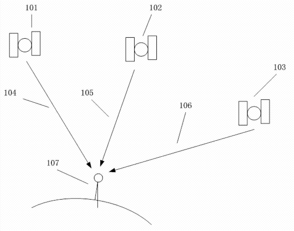
[0023] Such as figure 1 Shown is a schematic diagram of GPS acquisition, which includes: ground GPS receiver (referred to as "receiver") 107, GPS satellite (referred to as "satellite") 101, GPS satellite 102, GPS satellite 103, pseudo-range from receiver to satellite 101 104 , the pseudorange 105 from the receiver to the satellite 102 , and the pseudorange 106 from the receiver to the satellite 103 . The main process is that the center frequency of the 1 carrier signal ...


PUM


Abstract

The invention discloses a GPS (Global Positioning System) capture unit design method based on a matched filter. The GPS capture unit design method comprises the following steps: a GPS signal is changed into a mid-frequency digital signal after being subject to RF (Radio Frequency) front-end processing, and then the mid-frequency digital signal is re-quantified into a digital signal by a data quantification unit; the digital signal is changed into an orthogonal signal I and an orthogonal signal Q by a data orthogonal transformation unit; the orthogonal signal I and an orthogonal signal Q are further subjected to carrier stripping through a carrier NCO (Numerical Controlled Oscillator) and a complex multiplier to be changed into baseband signals close to zero frequency; a C/A code encoder generates a local C/A code; the locally generated C/A code is utilized to strip pseudo-codes in the orthogonal signal I and the orthogonal signal Q in MF (Medium Frequency) to complete coherent integration; and an FFT (Fast Fourier Transform) module transforms the coherent integration value to the frequency domain, outputs the frequency-domain amplitude values at 32 frequency points, then conduct noncoherent integration, and after that, outputs the maximum value, as well as a frequency point and a code phase, which correspond to the maximum value. The GPS capture unit design method increases the signal capture speed of a GPS receiver.

Description

technical field [0001] The invention belongs to the technical field of GPS communication, in particular to a method for capturing a GPS receiver, in particular to a method for designing a GPS capturing unit based on a matched filter (MF, Matched Filter). Background technique [0002] The new GPS, Galileo, and BD-2 signals have longer code lengths than GPS C / A codes, which help reduce cross-correlation between satellites and make satellite signals more robust against jamming. However, as the length of the code lengthens, the range of the search is also increasing when capturing. For these new pseudocodes, the traditional sequential capture algorithm is no longer applicable, because it will bring unbearable capture time. [0003] Parallel capture units that can greatly improve capture performance have been proposed in the past few years for military and indoor applications. These acquisition units are usually designed to only capture specific pseudo-codes and cannot capture ...

Claims


Application Information

Patent Timeline
IPC IPC(8): G01S19/30
Inventor 王镇杨军杨胜远卢培虞海宇蔡伟牛玉祥
Owner JIANGSU SEUIC TECH CO LTD
Why Eureka
Try Eureka