Infrared safety protection alarm device

A security protection and alarm device technology, applied in anti-theft alarms, alarms, instruments, etc., can solve problems such as failure to work normally and high false alarm rate, and achieve the effects of convenient anti-theft services, fast response speed, and high reliability

Inactive Publication Date: 2013-02-13
成都江法科技有限公司
View PDF7 Cites 8 Cited by
  • Summary
  • Abstract
  • Description
  • Claims
  • Application Information

AI Technical Summary

Problems solved by technology

In the past anti-theft systems, technical measures such as pyroelectric and microwave were generally used to collect human body intrusion signals. These have good results when applied indoors. The proposed measures have a very high rate of false alarms in actual use, and sometimes even fail to work properly

Method used


Image

  • Infrared safety protection alarm device
  • Infrared safety protection alarm device
  • Infrared safety protection alarm device

Examples


Embodiment Construction

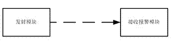
[0019] An infrared safety protection alarm device is characterized in that it includes an infrared transmitting circuit and an infrared receiving alarm circuit;

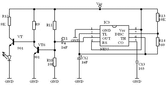
[0020] The infrared emission circuit includes an infrared light-emitting tube, a power supply Vcc, capacitors C11, C12, and C13, resistors R9, R10, R11, R12, R13, and R14, triodes VT, VT6, and a 555 oscillator chip. The 555 oscillator chip The trigger pin TL is grounded through the capacitor C12, the trigger pin TL of the 555 oscillator chip is connected to the threshold pin TH, the threshold pin TH is connected to the discharge terminal through the resistor R14, and the discharge terminal is connected to the power supply VCC through the resistor R13 , the control power terminal of the 555 oscillating chip is grounded through the capacitor R13, the output terminal OUT of the 555 oscillating chip is coupled with the base of the transistor VT6 through the capacitor C11, the base of the transistor VT6 is connected to VCC...


PUM


Abstract

The invention relates to the technical field of safety protection and provides an infrared safety protection alarm device. The device comprises an infrared transmitting circuit and an infrared receiving alarm circuit. The device disclosed by the invention is used for the technical field of safety protection.

Description

technical field [0001] The invention relates to the field of security technology and provides an infrared security protection alarm device. Background technique [0002] In industry and agriculture, fire protection, banking, hotels, shopping malls, aerospace and other departments, it is often necessary to monitor and alarm the environment to prevent theft. For banks, hotels, etc., anti-theft alarms are even more crucial. In the past anti-theft systems, technical measures such as pyroelectric and microwave were generally used to collect human body intrusion signals. These have good results when applied indoors. The proposed measures have a very high rate of false alarms in actual use, and sometimes even fail to work properly. [0003] We know that in the conventional environmental parameters, human intrusion detectors are very susceptible to changes in parameters due to the influence of the environment. With the maturity of infrared and laser technology, many infrared...

Claims


Application Information

Patent Timeline
Patent Type & Authority Applications(China)
IPC IPC(8): G08B13/183
Inventor 郭峻因
Owner 成都江法科技有限公司
Why Eureka
Try Eureka