
Remote water pressure monitoring method and system

A hydraulic and remote technology, applied in transmission systems, signal transmission systems, electrical components, etc., can solve the problems of harsh installation conditions, bulky, high power consumption, etc., and achieve high reliability, high speed, and low power consumption. Effect

Active Publication Date: 2014-04-02
SHANXI KEDA AUTOMATION CONTROL
View PDF2 Cites 0 Cited by
  • Summary
  • Abstract
  • Description
  • Claims
  • Application Information

AI Technical Summary

Problems solved by technology

[0003] The traditional water pressure monitoring method uses radio stations for data transmission. This method has certain defects: the sensing device is installed on the water supply pipeline, and the data transmission of the sensing device must be pulled to the control box outside the valve well. The control box Use the PLC to control the radio module, receive the data sent back by the sensor device and send the data to the control center through the radio station
In this way, the control box must be installed near the power supply equipment, and it cannot be too far away from the valve well, and the installation conditions are harsh; at the same time, the entire monitoring system is bulky, with low efficiency and high power consumption

Method used


Image

  • Remote water pressure monitoring method and system
  • Remote water pressure monitoring method and system
  • Remote water pressure monitoring method and system

Examples


Embodiment Construction

[0065] In order to make the object, technical solution and advantages of the present invention clearer, the present invention will be further described in detail below in conjunction with the accompanying drawings and embodiments. It should be understood that the specific embodiments described here are only used to explain the present invention, not to limit the present invention.

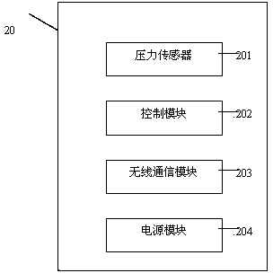
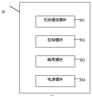
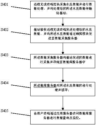
[0066] see figure 1 , the remote water pressure monitoring system proposed by the present invention is composed of remote wireless terminal equipment, a base station, a data acquisition server, a database server and an application server, wherein the remote wireless terminal equipment and the base station are used for direct point-to-point communication, and the remote wireless terminal equipment is collected back The method of uploading data to the network through the base station using GPRS wireless transmission.

[0067] The device adopts the following technical scheme: specifically, it includes ...


PUM


Abstract

The invention provides a remote water pressure monitoring system. The system comprises remote wireless terminal equipment, a base station, a data acquisition server, a database server and an application server, wherein the remote wireless terminal is used for acquiring water pressure data on the spot and transmitting the acquired water pressure data to the base station; the base station is used for communicating with the remote wireless terminal equipment in one-to-one manner, receiving the water pressure data sent from the remote wireless terminal equipment and sending the water pressure data to the data acquisition server through a honeycomb module; the data acquisition server is used for acquiring the data sent by the base station and storing the data in the database server; the database server is used for finishing the processing and caching of the water pressure data and notifying a client to finish data report after confirming that the data storage is normal; and the application server is used for providing data services to the client application, including inquiry, updating, indexing, caching, inquiry optimization, safety and multi-user access control and alarm. The water pressure monitoring system provided by the invention has the characteristics of low power consumption, high speed and high reliability, and saves the material and data transmission cost; and due to a wireless transmission function, the equipment mounting and debugging are not limited by environments, and the equipment can be mounted and used in various environments.

Description

technical field [0001] The invention relates to a remote wireless monitoring system, in particular to a remote water pressure monitoring system. Background technique [0002] Traditional waterworks need to monitor the water pressure of the main water supply pipes and branch pipes in order to monitor and control whether the tap water can meet the pressure required to reach the user's floor. If the water pressure on the main pipe and branch pipes is low, some users may If there is a problem with the water supply, it is necessary to increase the pressure of the water in the pipeline. Waterworks often use the method of manually going into the well. Workers enter the valve well to observe the pressure measuring instrument installed on the water supply pipeline to read the pressure value and return the data. This method is very inconvenient and wastes human and material resources. Moreover, when the water supply pipeline breaks, it cannot be detected in time, and countermeasures ...

Claims


Application Information

Patent Timeline
Patent Type & Authority Patents(China)
IPC IPC(8): G08C17/00H04L29/08
Inventor 高波梁耀林贾华忠杜文卓
Owner SHANXI KEDA AUTOMATION CONTROL
Learn More