Flash synchronization demonstration system and demonstration method of complex network

A complex network, synchronous demonstration technology, applied in the field of teaching instruments, can solve problems such as the inability to display the network topology structure, the inability to display the influence of the network structure and parameter synchronization performance, etc., and achieve an easily acceptable effect.

Inactive Publication Date: 2013-02-13
UNIV OF SHANGHAI FOR SCI & TECH
View PDF3 Cites 6 Cited by
  • Summary
  • Abstract
  • Description
  • Claims
  • Application Information

AI Technical Summary

Problems solved by technology

The laboratory of a university in the United States uses multiple micro-robots to demonstrate the phenomenon of flash synchronization, but their method cannot show the network topology, that is, the coupling relationship between the micro-robots, so it is impossible to show the network structure and parameters on the synchronization performance. influences

Method used


Image

  • Flash synchronization demonstration system and demonstration method of complex network
  • Flash synchronization demonstration system and demonstration method of complex network
  • Flash synchronization demonstration system and demonstration method of complex network

Examples


Embodiment 1

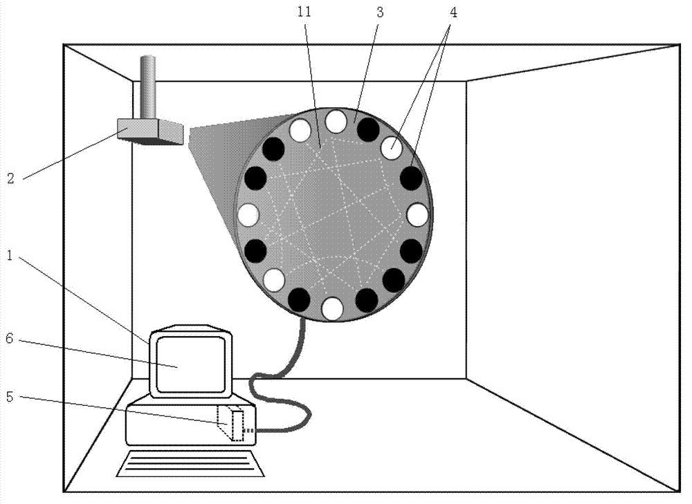
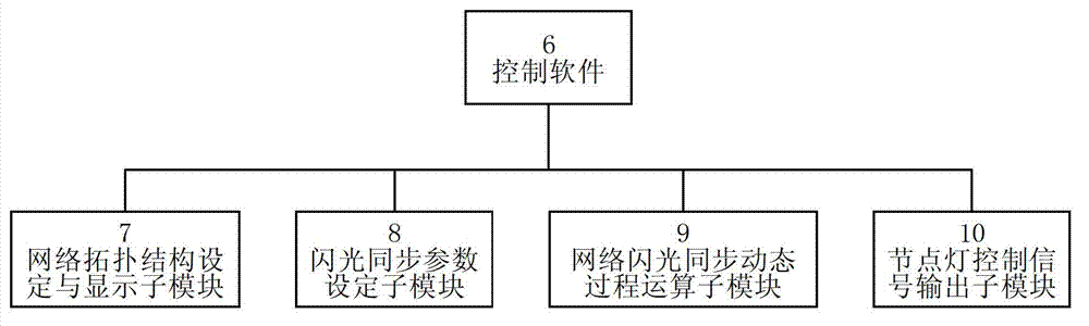
[0019] The control computer system (1) is an industrial control computer, the network topology projection board (3) is a circular board, and 16 node lamps (4) form a circle and are installed on the edge of the network topology projection board (3), and the projector ( 2) It is connected to the industrial control computer and installed on the ceiling. The picture of the projector (2) is projected to the circular area in the center of the network topology projection board (3). A digital output interface board is installed inside the industrial control computer as a node light drive circuit module (5), see figure 1 . The control software (6) is written by LabView, including the network topology setting and display submodule (7), the flash synchronization parameter setting submodule (8), the network flash synchronization dynamic process operation submodule (9) and the node light control signal output submodule (10), see figure 2 . The node lamp control signal output sub-module...

Embodiment 2

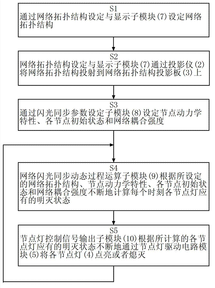
[0021] The control computer system (1) is an embedded computer, the control software (6) is written in C language, and the projector (2) is installed on the bracket together with the embedded computer. There are 100 node lights, which are arranged in a square frame and installed on the network topology projection board. The node lights are numbered, and the connection lines projected between the node lights are solid lines with arrows. In the flash synchronization parameter setting sub-module (8), the dynamic characteristics of the nodes are selected and set by selecting one of multiple options. The steps of the demonstration method are the same as image 3 .


PUM


Abstract

The invention discloses a flash synchronization demonstration system and a flash synchronization demonstration method of a complex network; the system is characterized in that a plurality of lamps enclosed in a circle are used to indicate network nodes, lines projected from the lamps by a projector are used to indicate connected edges of the network, and on and off states of the lamps controlled by a computer are used to indicate the states of the nodes; the method comprises the steps of setting dynamic characteristics and initial states of network structures, network parameters and the nodes by a computer software, obtaining the state of each node at each hour of the synchronization transition process by real-time computing of the software and then controlling the on and off states of the node lamps by a driving circuit module, thereby demonstrating the flash synchronization process of the complex network. The system and the method have the advantages that a network topological structure and the flash synchronization process of the topological structure can be displayed simultaneously, so that the students can observe the impact of the network structures and the network parameters on synchronization stability and transition process conveniently; as a teaching apparatus, the system enables the synchronization phenomena of the complex network to be vivid and intuitional and enables the knowledge to be interesting and easily acceptable.

Description

technical field [0001] The invention belongs to the field of teaching instruments, in particular to a complex network flash synchronous demonstration system and demonstration method. Background technique [0002] Complex networks are the forms of existence of nature and society. Synchronous phenomena on complex networks are important scientific knowledge. Many schools have opened courses in this area. The related teaching content includes the explanation of synchronous phenomena, the stability of synchronous behavior, and the process of synchronous transition. Analysis, impact of network structure and parameters on synchronization performance, and more. At present, the teaching of this knowledge is mainly implemented through mathematical formula expression, picture display, curve description and a small amount of software simulation. These only teaching methods make the originally wonderful network synchronization phenomenon abstract and difficult to understand. Flash synch...

Claims


Application Information

Patent Timeline
Patent Type & Authority Applications(China)
IPC IPC(8): G09B19/00
Inventor 刘歌群郭东逸辛辰李文惠任冠琦朱春香马小美江琨郝陈祥
Owner UNIV OF SHANGHAI FOR SCI & TECH
Why Eureka
Try Eureka