Shifting register as well as driving method thereof, grid electrode driving device and display device

A technology for shift registers and gates, which is applied in the field of gate drive devices and display devices, shift registers and their drives, and can solve problems such as high power consumption and complex gate drive structure, so as to reduce power consumption and simplify gate The effect of pole-driven structure

Inactive Publication Date: 2013-02-13
BOE TECH GRP CO LTD
View PDF4 Cites 27 Cited by
  • Summary
  • Abstract
  • Description
  • Claims
  • Application Information

AI Technical Summary

Problems solved by technology

[0004] However, in the existing gate drive structure, the output of the Nth row is mostly used as the reset signal of the N-1th row, which leads to the complexity of the existing gate drive structure and the problem of high power consumption.

Method used


Image

  • Shifting register as well as driving method thereof, grid electrode driving device and display device
  • Shifting register as well as driving method thereof, grid electrode driving device and display device
  • Shifting register as well as driving method thereof, grid electrode driving device and display device

Examples


Embodiment Construction

[0067] In order to make the purpose, technical solutions and advantages of the embodiments of the present invention more clear, the embodiments of the present invention will be further described in detail below in conjunction with the embodiments and the accompanying drawings. Here, the exemplary embodiments and descriptions of the present invention are used to explain the present invention, but not to limit the present invention.

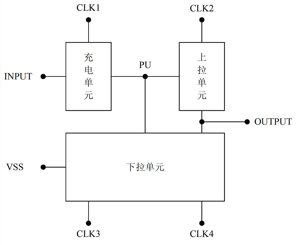
[0068] The embodiment of the present invention provides a shift register, as attached figure 1 As shown, it can specifically include:

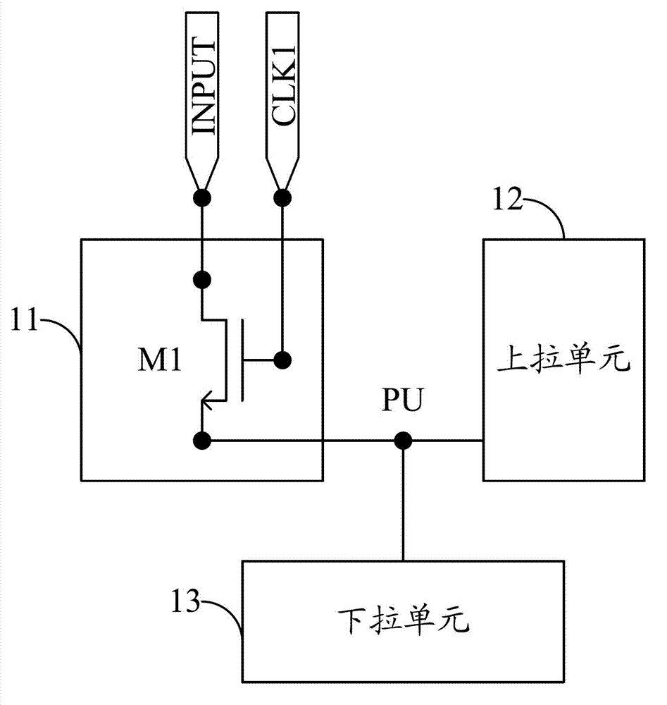
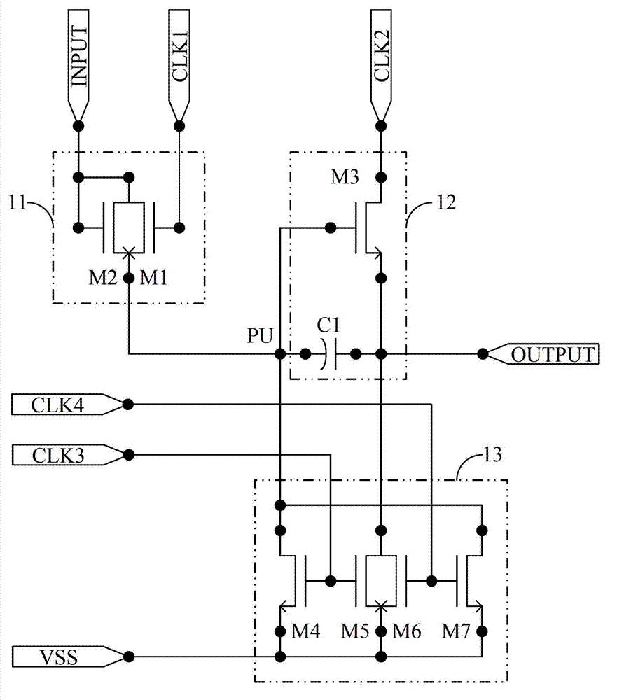
[0069] Charging unit 11, pull-up unit 12, pull-down unit 13, gate signal input terminal INPUT, DC low-level signal input terminal VSS, first clock signal input terminal CLK1, second clock signal input terminal CKL2, third clock signal input terminal CLK3, the fourth clock signal input terminal CLK4, and the gate signal output terminal OUTPUT. in:

[0070] The charging unit 11 can be connected to the gate signal ...


PUM


Abstract

The invention provides a shifting register as well as a driving method thereof, a grid electrode driving device and a display device, wherein a charging unit, an upwards pulling unit, a downwards pulling unit, a grid electrode signal input end, a DC (direct current) low-level signal input end, a grid electrode signal output end and first, second, third and fourth clock signal input ends are arranged in the shifting register, so that the grid electrode driving structure is simplified and the power consumption for driving a grid electrode is reduced.

Description

technical field [0001] The present invention relates to the display field, in particular to a shift register, a driving method thereof, a gate driving device and a display device. Background technique [0002] In the flat panel display, the basic principle of realizing a frame display is to output the data signal required by each row of pixels from top to bottom through the Source driver (source driver), and the Gate driver (gate driver) from top to bottom in turn A square wave with a certain width is input to each row of pixel gates for gating. [0003] In the existing production process, the gate drive IC (integrated circuit) and the source drive IC are bonded (bonded) on the glass panel through the COG (Chip On Glass, fixing the chip on the glass) process. [0004] However, in the existing gate driving structure, the output of the Nth row is mostly used as the reset signal of the N-1th row, which leads to the complexity of the existing gate driving structure and the prob...

Claims


Application Information

Patent Timeline
Patent Type & Authority Applications(China)
IPC IPC(8): G09G3/20G09G3/36G09G3/32G11C19/28
CPCG11C19/28G09G2310/0286
Inventor 刘尧虎
Owner BOE TECH GRP CO LTD
Why Eureka
Try Eureka