Broadband bionic yagi antenna with low radar cross section

A radar cross-section and Yagi antenna technology, applied in the field of bionic antennas, can solve the problems of unfavorable antenna stealth and increased radar cross-section, and achieve the effects of easy stealth, low radar cross-section, and broadband characteristics

Inactive Publication Date: 2013-02-13
XIDIAN UNIV
View PDF3 Cites 26 Cited by
  • Summary
  • Abstract
  • Description
  • Claims
  • Application Information

AI Technical Summary

Problems solved by technology

Although the antenna has a good working frequency band, the radiation unit, director and reflector increase the radar cross-section, which is not conducive to the stealth of the antenna

Method used


Image

  • Broadband bionic yagi antenna with low radar cross section
  • Broadband bionic yagi antenna with low radar cross section
  • Broadband bionic yagi antenna with low radar cross section

Examples


Embodiment Construction

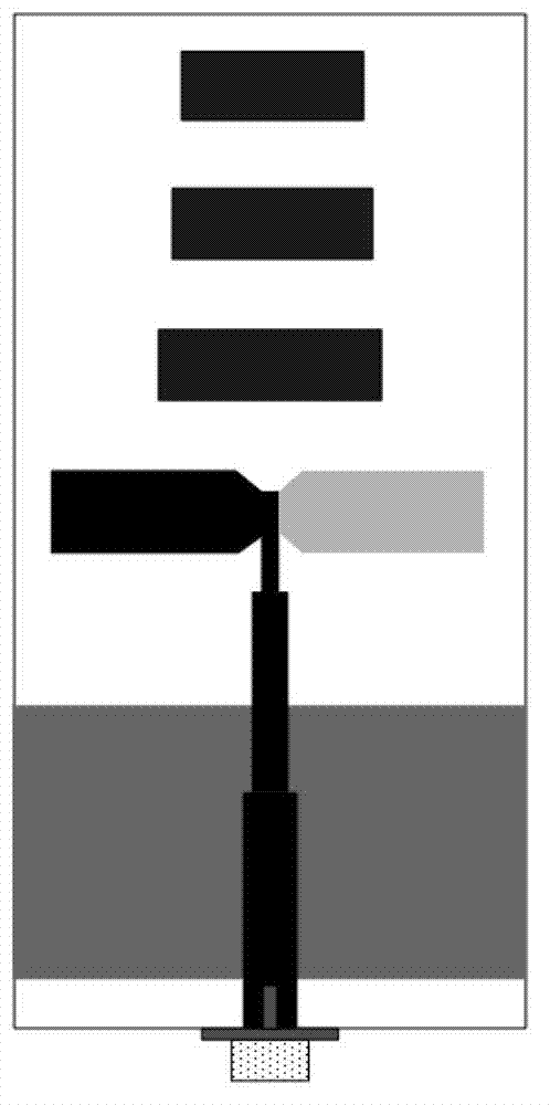
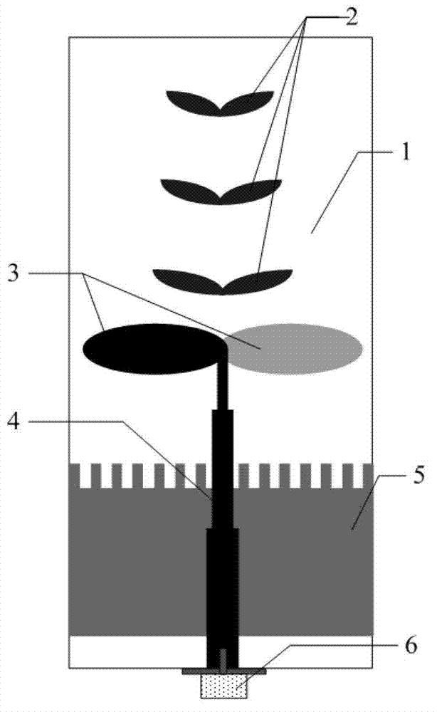
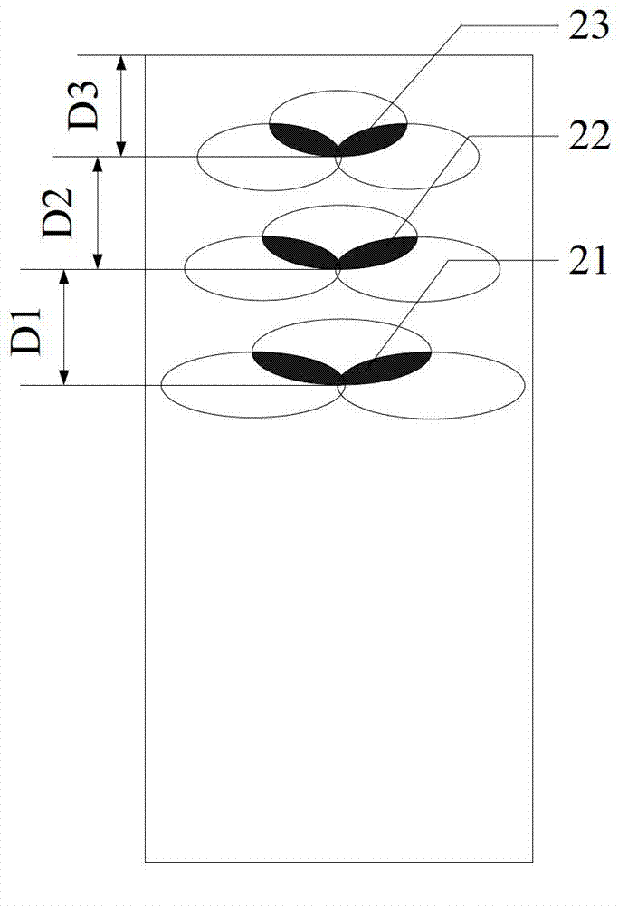
[0030] refer to figure 2 , the present invention is mainly composed of a double-layer dielectric material plate 1, three directors 2, two radiation units 3, parallel strip lines 4, a reflector 5 and a coaxial conversion joint 6. Three directors 2 are printed on the topmost layer of the double-layer dielectric material board 1, two radiation units 3 are printed on the topmost layer and the bottommost layer of the double-layer dielectric material board 1, and the reflector 5 is printed on the double-layer dielectric material board 1. Between the two layers of the material plate 1. The two radiation units 3 are respectively welded to the inner core and the outer core of the coaxial conversion joint 6 through parallel strip lines 4 . The structures of the three directors 2 are as follows: image 3 As shown, the structure of the two radiating units 3 and the parallel strip line 4 is as follows Figure 4 As shown, the structure of the reflector 5 is as Figure 5 shown.

[0031...


PUM


Abstract

The invention discloses a broadband bionic yagi antenna with a low radar cross section and mainly solves the problems of high radar cross section and relatively narrow band width in the traditional yagi antenna. The antenna simulates an opposite phyllotaxis plant leaf structure and comprises a director (2), a radiating element (3), a parallel strip line (4), a reflector (5) and a coaxial conversion joint (6). The radiating element (3) is of an oval structure, the director (2) simulates a feather-shaped leaf structure, and the reflector (4) is a rectangle patch with a tooth-shaped structure. The radiating element (3) is printed on a top layer and a bottom layer of a double-layer medium material plate (1) and respectively connected with an inner core and an outer core of the coaxial conversion joint (6) by the parallel strip line (4); the director (2) is printed on the top layer of the double-layer medium material plate (1); and the reflector (4) is printed between two layers of the double-layer medium material plate (1). The broadband bionic yagi antenna with the low radar cross section has the advantages of wide frequency band and good invisibility performance and can be used on an invisible target carrier.

Description

technical field [0001] The invention belongs to the technical field of antennas, in particular to a bionic antenna which can be used for stealth and broadband end-fire reception and transmission. Background technique [0002] Radar cross section RCS is one of the most basic parameters to characterize the identifiable characteristics of targets in radar detection technology, stealth and anti-stealth technology, and it is a measure of the return power of a target in a given direction under the illumination of a plane wave. Radar cross-section reduction is to control and reduce the radar cross-section of military targets, reduce the combat effectiveness of enemy electronic detection systems and weapon platforms, and improve the penetration and survivability of military targets. How to reduce the radar cross section of the target and how effective the reduction is is of great significance to the victory or defeat of the war in the complex electromagnetic environment we are curre...

Claims


Application Information

Patent Timeline
Patent Type & Authority Applications(China)
IPC IPC(8): H01Q1/38H01Q19/10
Inventor 刘英薛金阳易浩洪涛姜文王伟
Owner XIDIAN UNIV
Why Eureka
Try Eureka