Quasi-proportional resonant control method for parallel active power filter

A power filter and quasi-proportional resonance technology, which is applied to harmonic reduction devices and AC networks to reduce harmonics/ripples, etc., can solve the problems that proportional resonance control cannot meet the requirements, poor adaptability, and failure to achieve control effects, etc.

Active Publication Date: 2015-12-23
南京国电南自新能源科技有限公司
View PDF5 Cites 0 Cited by
  • Summary
  • Abstract
  • Description
  • Claims
  • Application Information

AI Technical Summary

Problems solved by technology

However, when the grid frequency fluctuates, the conventional proportional resonance control cannot meet the requirements and has poor adaptability
The traditional proportional resonance control is an improvement of the proportional resonance control, but it does not achieve the best control effect

Method used


Image

  • Quasi-proportional resonant control method for parallel active power filter
  • Quasi-proportional resonant control method for parallel active power filter
  • Quasi-proportional resonant control method for parallel active power filter

Examples


Embodiment Construction

[0023] Below in conjunction with accompanying drawing, the present invention will be further described

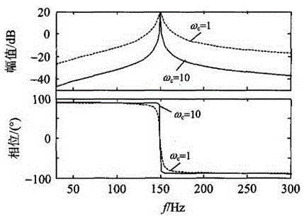
[0024] The transfer function of the quasi-proportional resonant controller in the complex domain is shown in formula (1):

[0025] G ( s ) = K p + 2 K i ω c s s 2 + 2 ω c s + ω h 2 - - - ( 1 )

[0026] K p —Scale factor

[0027] K i —Generalized integral coefficient

[0028] ω h — Resonan...


PUM


Abstract

The invention discloses a quasi proportional resonance control method and control system for a parallel active power filter. A quasi proportional resonance controller is used for monitoring the voltage frequency of a power grid in real time by a phase-locked loop; when the voltage frequency of the power grid fluctuates, a value of parameter omega h in the controller is corrected in real time to be matched with the fluctuation of the frequency of the power grid; and the resonance frequency is always kept to be integral times the actual frequency of the power grid. Therefore, the control system can always maintain the maximum grain output and ensure the optimal control effect.

Description

technical field [0001] The invention relates to a control method and control system hardware of a parallel source power filter, and belongs to the technical field of medium and low voltage power electronics. Background technique [0002] Since the 1970s, the power electronic equipment in the grid has been increasing, resulting in serious grid pollution. This is mainly due to the non-linear, impact and unbalanced power consumption characteristics of these loads. Therefore, the active power filter technology for harmonic suppression has become one of the research hotspots in the field of power electronics and electrotechnical. [0003] Active Power Filter (APF) starts from the outside and uses real-time compensation technology to improve the power supply quality of the power grid. It is a harmonic compensator. Compared with the traditional passive power filter, the compensation method of APF is more flexible. It can compensate the harmonics whose frequency and size are const...

Claims


Application Information

Patent Timeline
Patent Type & Authority Patents(China)
IPC IPC(8): H02J3/01
CPCY02E40/40
Inventor 刘瑾丁明进石春虎钱诗宝李冰
Owner 南京国电南自新能源科技有限公司
Why Eureka
Try Eureka