
Detection and mitigation of interference in a receiver

A technology of receiving equipment and receiving method, applied in receiver monitoring, shaping network in transmitter/receiver, space transmit diversity, etc., can solve the problems of indistinguishable, inability to fully optimize receiver performance, etc.

Active Publication Date: 2015-04-08
SPREADTRUM COMM (SHANGHAI) CO LTD
View PDF7 Cites 0 Cited by
  • Summary
  • Abstract
  • Description
  • Claims
  • Application Information

AI Technical Summary

Problems solved by technology

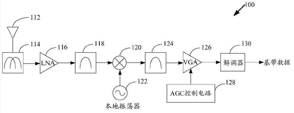
However, this prior art approach does not selectively use wideband detection and therefore cannot distinguish out-of-band interference, that is, interference a few channels away, from adjacent interference in adjacent or adjacent channels
Therefore, the architecture cannot fully optimize the performance of the receiver

Method used


Image

  • Detection and mitigation of interference in a receiver
  • Detection and mitigation of interference in a receiver
  • Detection and mitigation of interference in a receiver

Examples


Embodiment Construction

[0023] This description of exemplary embodiments is intended to be read in conjunction with the accompanying drawings, which are to be considered a part of the entire specification as written.

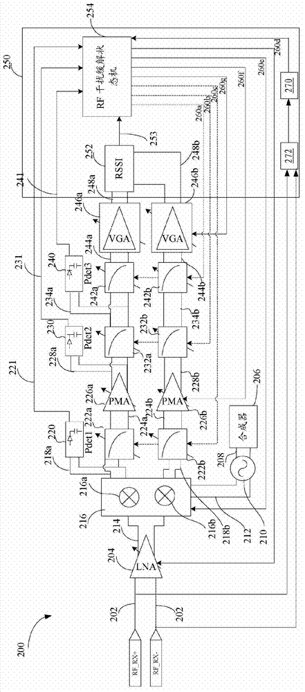
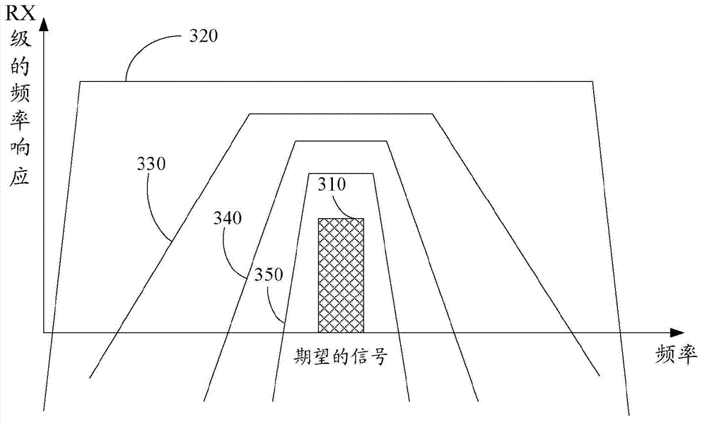
[0024] Embodiments of the present disclosure provide a novel receiver architecture to optimize receiver performance in the presence of interference. In various embodiments, the estimation circuit is used in a variable selective manner to determine the exact nature of the interference and to optimize performance accordingly. Variable selectivity is achieved by using multiple stages of filtering with progressively narrower bandwidths. Furthermore, the novelty of the actual method of optimizing receiver performance compared to the prior art is that the gain setting and baseband filter order (to be used class).

[0025] figure 2 is a block diagram of the system architecture of the receiver 200 according to some embodiments of the present disclosure. An input signal 202 is received, fo...


PUM


Abstract

A receiver architecture optimizes receiver performance in the presence of interference. In various embodiments, power estimation circuits are used with variable selectivity to determine the exact nature of the interference and to optimize the performance correspondingly. The variable selectivity is achieved using stages of filtering with progressively narrower bandwidths. Also, the actual method of optimizing the receiver performance is an improvement compared to the traditional techniques in that the gain settings and the baseband filter order (stages to be used) will be optimized based on the nature of the interference as determined by the power detector measurements. For a device such as a cellular phone that operates in a dynamic and changing environment where interference is variable, embodiments advantageously provide the capability to modify the receiver's operational state depending on the interference.

Description

technical field [0001] The present disclosure relates to receiver architectures in communication systems, and more particularly, some embodiments relate to methods and apparatus for detecting and mitigating interference and optimizing receiver performance. Background technique [0002] Radio frequency transceivers in cellular systems typically receive and decode the desired signal in the presence of interference, which often entails compromising receiver performance. For example, to prevent clipping due to interference, several stages of narrow analog filters are often found in conventional receiver designs. Such filters add current drain and distort the desired signal, thereby degrading receiver performance. Furthermore, the active stages of the receiver, especially the radio frequency (RF) stage, are designed to have a high level of linearity so that distortion is minimized in the presence of interference. This linearity generally requires relatively high bias conditions...

Claims


Application Information

Patent Timeline
Patent Type & Authority Patents(China)
IPC IPC(8): H04B7/08H04L25/03
CPCH04B17/327H04B1/123H04B17/008H03G3/3078H04B17/29H04L25/03057H04B1/1027H04L43/16
Inventor 许志刚大卫·豪布
Owner SPREADTRUM COMM (SHANGHAI) CO LTD
Learn More