Spectral plane method and apparatus for wavelength-selective optical switching

a wavelength-selective optical switching and spectral plane technology, applied in the field of optical communication, can solve the problems of limited flexibility in the choice of wavelength(s) to be dropped or added, not dynamically re-configurable, and large number of constituent parts, and achieve the effect of high degree of flexibility

Inactive Publication Date: 2005-04-07
WILSON GORDON +1
View PDF1 Cites 47 Cited by
  • Summary
  • Abstract
  • Description
  • Claims
  • Application Information

AI Technical Summary

Benefits of technology

[0008] The present invention describes a novel multi-input/output variable bandwidth tunable optical filtering device and a method to operate the same as a ROADM in optical

Problems solved by technology

Unfortunately however, this method offers limited flexibility in choice of wavelength(s) to be dropped or added and is not dynamically re-configurable.
Although such a device allows for any combination of channels to be added and dropped, it requi

Method used


Image

  • Spectral plane method and apparatus for wavelength-selective optical switching
  • Spectral plane method and apparatus for wavelength-selective optical switching
  • Spectral plane method and apparatus for wavelength-selective optical switching

Examples


Embodiment Construction

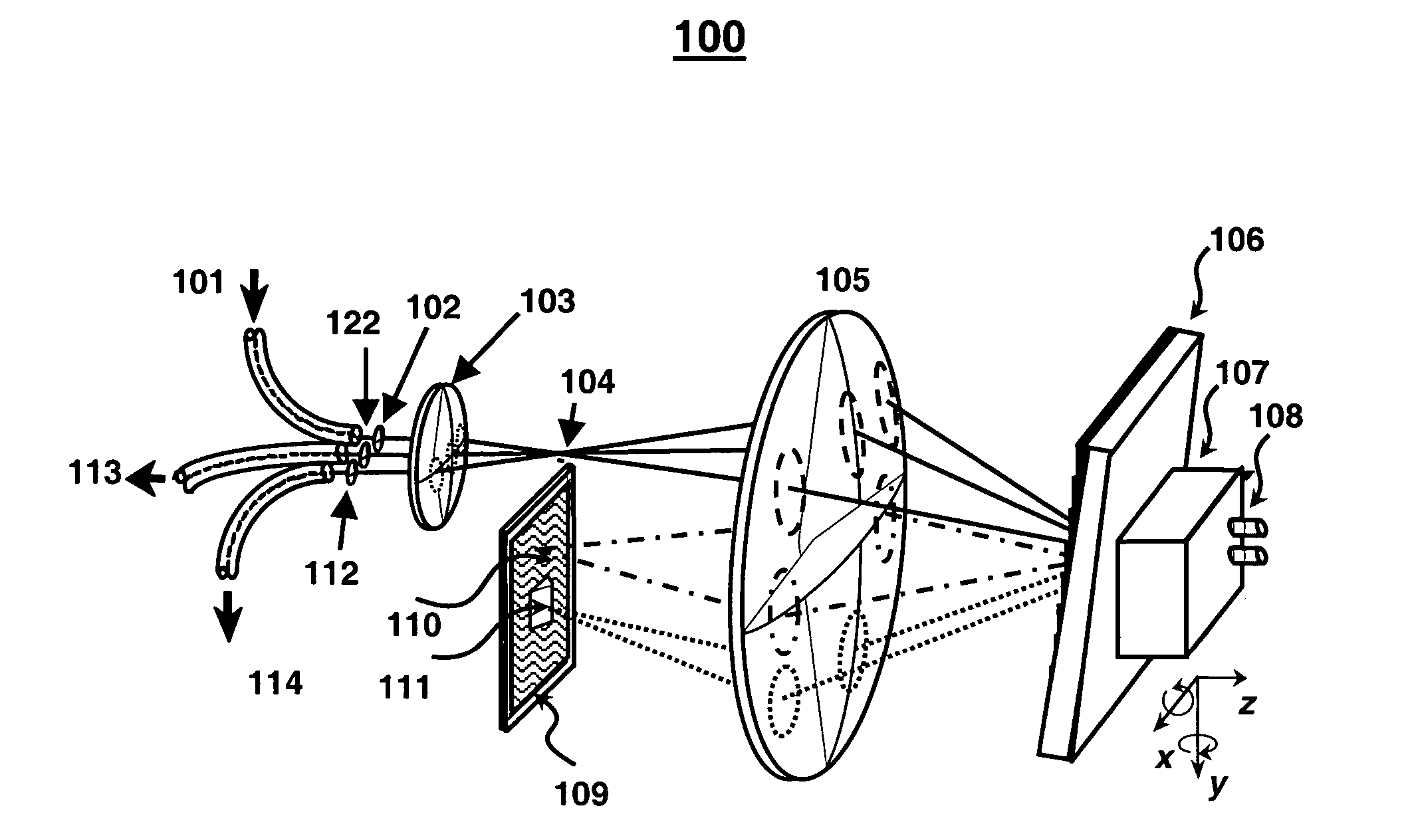
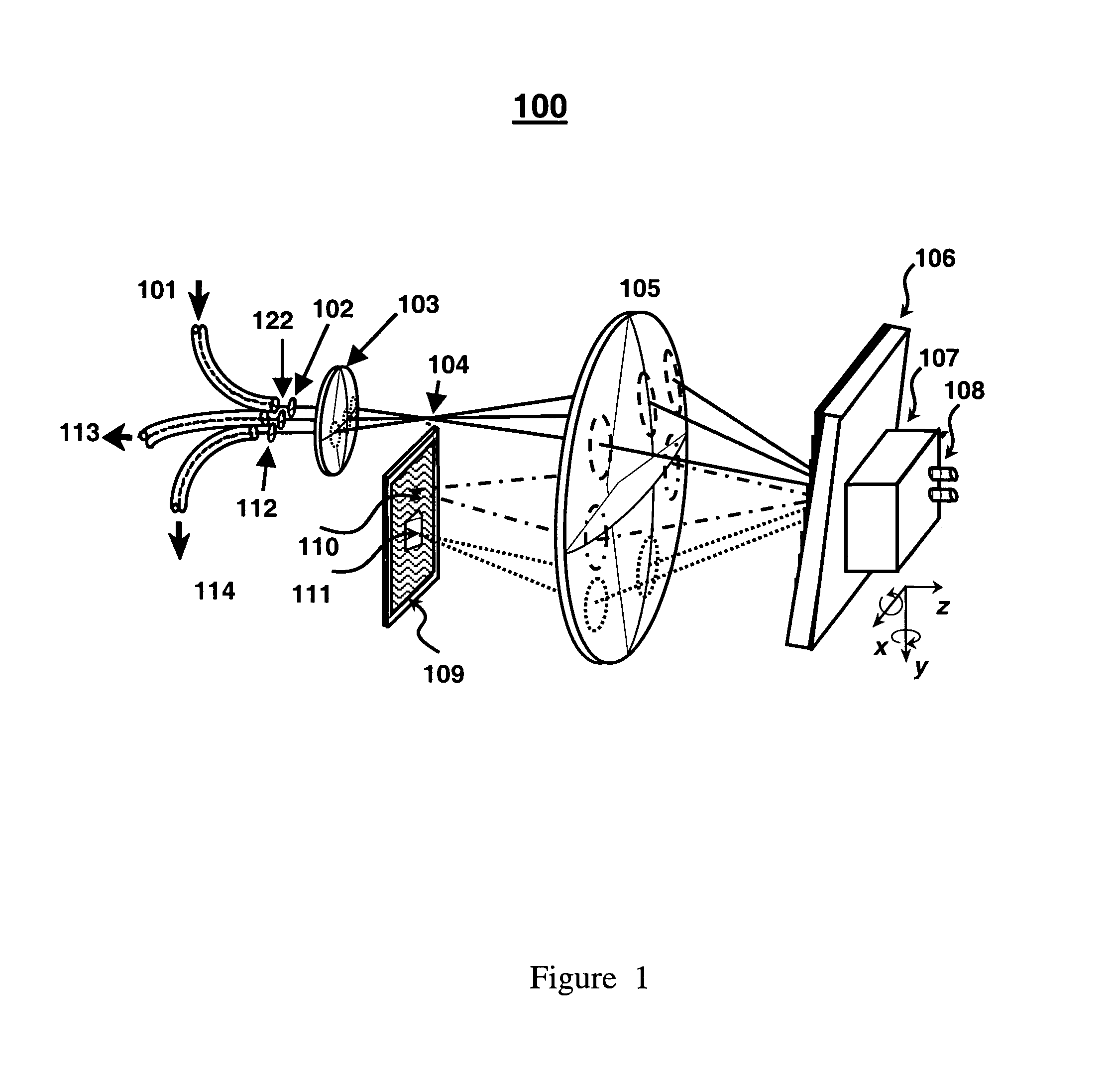
[0032]FIG. 1 illustrates the basic concept of the optical filtering device of the present invention. Three optical fibers 101, 113 and 114 connect to the optical system 100, however, the configuration shown here can be scaled to larger number of input and / or output fibers. Any of the three fibers can be used as an input or an output port of the device. For illustrative purposes 101 is depicted as the sole input fiber.

[0033] With continued reference now to FIG. 1, multi-wavelength optical input signal carried on optical fiber 101 exits the end facet and is collimated by a micro-optic lens 102. The collimated beam passes through a second micro-optic lens 103 slightly off-center from the optical axis so that the input signal is focused to a focal point 104 at an angle to the optical axis forming the source for the spectrally dispersive image system. The combination of the micro-lenses 102 and 103 may result in an anamorphic optical system producing either a symmetrical or asymmetrical...


PUM


Abstract

We describe a variable bandwidth tunable optical spectral filtering device and associated method for selectively directing a portion of a wavelength multiplexed input signal, entering through one or more optical fibers, into one or more output signals provided to one or more optical fibers and/or electronic outputs. The optical filtering is accomplished using free-space diffractive wavelength de-multiplexing optics combined with a fixed (permanent) patterned structure located in the spectrally dispersed image plane. The structure can direct a selected spectral portion of the optical signal to one or more separate outputs, such as an optical fiber or power detector. A single active element in the optical path is used to spatially shift, or steer, the entire input spectrum at the dispersed spectral image plane, to control the portion of the input spectrum illuminating specific features on the permanent patterned structure. In one preferred embodiment, a device with a fixed selective area triangular shaped tilted reflective facet on a flat reflective surface is constructed such that the light reflected off the flat reflective surface and off the triangular reflective facet are selectively multiplexed back and directed to different output fiber ports. Inputs at different angles of incidence on the reflective structures may be deflected by the same structures to different output port fiber ports. A reconfigurable variable-bandwidth tunable optical add/drop multiplexing device is constructed using such a filtering device and an application of such an add/drop multiplexing in a optical transport network is demonstrated.

Description

FIELD OF THE INVENTION [0001] This invention relates generally to the field of optical communications and in particular to a variable bandwidth tunable optical filtering device for selectively dropping or adding optical signal channels as a function of wavelength out of multi-channel optical signal transmitted through a multi-node optical communication network. BACKGROUND OF THE INVENTION [0002] In a Wavelength Division Multiplexed (WDM) optical communication network, a multiplexed optical signal at different wavelengths is transmitted between different network nodes of the network. Optical add / drop multiplexing (OADM) in a network allows connections to be made selectively between any two, but not necessarily restricted to two, different network nodes without disturbing the communication anywhere in the rest of the network. [0003] In a simple OADM called a fixed OADM (FOADM), a fixed band-pass filter is used to selectively drop channels at a “drop” port or add optical signal channel...

Claims


Application Information

Patent Timeline
IPC IPC(8): G02B6/34
CPCG02B6/2931G02B6/29313G02B6/356G02B6/29383G02B6/3512G02B6/29314
Inventor WILSON, GORDONFORD, JOSEPH E.
Owner WILSON GORDON
Why Eureka
Try Eureka