Circuit with Q-enhancement cell having feedback loop

a qenhancement cell and feedback loop technology, applied in the field of qenhancement cells, can solve the problems of poor performance at the upper and lower frequencies within the bandwidth

Active Publication Date: 2008-07-15
AVAGO TECH INT SALES PTE LTD
View PDF9 Cites 43 Cited by
  • Summary
  • Abstract
  • Description
  • Claims
  • Application Information

AI Technical Summary

Benefits of technology

[0004]In one example embodiment, an amplitude feedback loop comprises an RF amplifier, a detector, a comparator, and a Q-enhancement cell. In an example embodiment, the RF amplifier has an output signal, and the detector has an input coupled to the output signal of the RF amplifier and configured to detect a level of the output signal of the RF amplifier. The comparator circuit may be coupled to receive as inputs a reference voltage and the output of the detector, and the comparator circuit may be configured to output a control signal based on a difference between the reference voltage and the output signal of the power detector. The Q-enhancement cell may be coupled to the RF amplifier and have an input coupled to an output of the comparator circuit. A bias current of the Q-enhancement cell may be adjusted based on the control signal output by the comparator circuit.

Problems solved by technology

Channel selection within these frequency bandwidths often results in poor performance at the upper and lower frequencies within the bandwidth.

Method used


Image

  • Circuit with Q-enhancement cell having feedback loop
  • Circuit with Q-enhancement cell having feedback loop
  • Circuit with Q-enhancement cell having feedback loop

Examples


Embodiment Construction

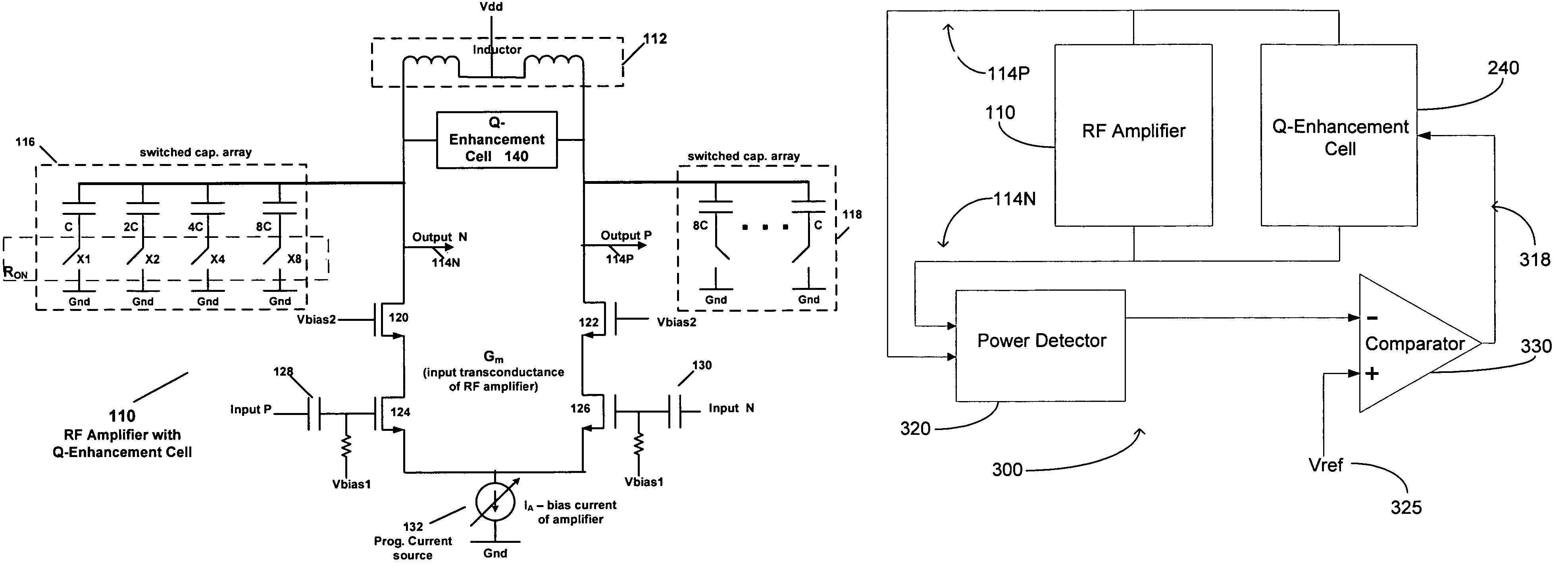
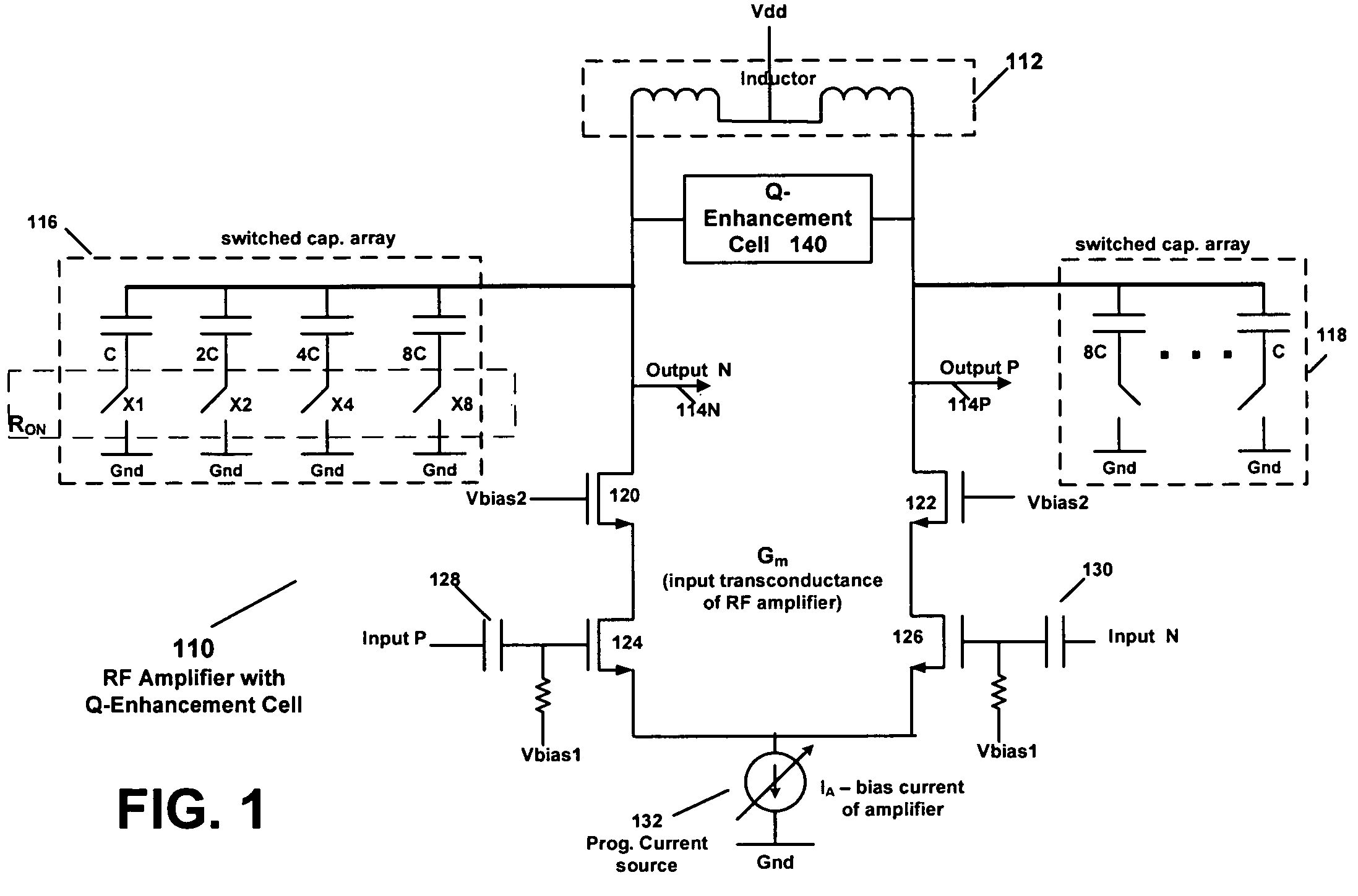
[0013]FIG. 1 is a block diagram of an amplifier circuit according to an example embodiment. The amplifier 110 in FIG. 1 is merely an example circuit used to illustrate some operation and features of an example embodiment. The various techniques and features described in this disclosure may apply to a wide variety of circuits, and an amplifier is merely one example circuit where these techniques may be applied.

[0014]Amplifier 110 may be a differential amplifier, e.g., may include differential (e.g., positive and negative) inputs and may include differential outputs, and may be an RF amplifier in an example embodiment. Amplifier 110 may include cascode devices or transistors 120 and 122. A bias voltage (Vbias2) may be applied to the gates of both cascode transistors 120 and 122. Amplifier 110 may also include a transistor 128 coupled in series with cascode transistor 120, and a transistor 126 coupled in series with cascode transistor 122. A positive input (input P) may be applied to t...


PUM


Abstract

According to an example embodiment, an amplitude feedback loop may include an RF amplifier, a detector, a comparator, and a Q-enhancement cell. In an example embodiment, the RF amplifier has an output signal, and the detector has an input coupled to the output signal of the RF amplifier and is configured to detect a level of the output signal of the RF amplifier. The comparator circuit may receive as inputs a reference voltage and the output of the detector. Also, the comparator circuit is configured to output a control signal based on a difference between the reference voltage and the output signal of the power detector. The Q-enhancement cell may be coupled to the RF amplifier and have an input coupled to an output of the comparator circuit. A bias current of the Q-enhancement cell may be adjusted based on the control signal output by the comparator circuit.

Description

CROSS-REFERENCE TO RELATED APPLICATIONS[0001]This application is a continuation-in-part of U.S. patent application Ser. No. 11 / 510,373, filed on Aug. 25, 2006, entitled “Circuit with Q-Enhancement cell Having Programmable Bias Current Slope,” hereby incorporated by reference. This application also claims priority to U.S. Provisional application Ser. No. 60 / 835,482, filed on Aug. 3, 2006, entitled “Circuit with Q-Enhancement cell Having Programmable Bias Current Slope,” hereby incorporated by reference.BACKGROUND[0002]Wireless transceivers and other circuits are used in a wide variety of wireless and communication systems. A wireless transceiver may typically include a wireless receiver for receiving and demodulating signals, and a transmitter for modulating signals for transmission. The transceiver may typically include a variety of RF (radio frequency) circuits, such as amplifiers, mixers, filters, LO (local oscillator) circuits, etc. The RF amplifiers typically have to operate ove...

Claims


Application Information

Patent Timeline
Patent Type & Authority Patents(United States)
IPC IPC(8): H03F3/04
CPCH03F1/42H03F1/56H03F3/191H03F3/45188H03H11/1291H03H11/1213H03F2200/451H03F2200/78H03F2203/45521H03F2203/45606H03F2203/45626H03F2200/465
Inventor OJO, ADEDAYOBEHZAD, ARYA
Owner AVAGO TECH INT SALES PTE LTD
Why Eureka
Try Eureka