Combine harvester control device and method

A combine harvester and control device technology, applied in the direction of harvesters, cutters, agricultural machinery and implements, etc., can solve the problems of increasing the difficulty of control, clogging of threshing drums, affecting the effect of control, etc., to improve dynamic control performance, Improved control performance, increased stability and harvesting efficiency results

Active Publication Date: 2013-02-20
江苏大学扬州(江都)新能源汽车产业研究所
View PDF6 Cites 8 Cited by
  • Summary
  • Abstract
  • Description
  • Claims
  • Application Information

AI Technical Summary

Problems solved by technology

At present, the structure of the combine harvester still has some deficiencies from the control point of view: First, on the traditional combine harvester, since the transmission speed of the conveyor belt is not affected by the walking speed of the combine harvester, the system structure is expressed as A pure hysteresis link with a large time constant, that is, the feeding amount of the threshing drum will not change immediately with the change of driving speed, but it will take a period of delay before the feeding amount of the drum will change, thus increasing the control. Difficulty, which seriously affects the effect of control
If the transmission speed of the conveyor belt can be controlled by the walking speed of the combine harvester, the pure lag link can be eliminated, or it can be transformed into a pure lag link with a small time constant, which will greatly improve the performance of the control; secondly, now Some combine harvesters often only use control methods to adjust the driving speed based on the information such as the rotational speed of the threshing drum, so as to realize the stability of the operating load. Exceeding the standard, that is, the active torque provided by the engine for the drum is already smaller than the load torque. Even if the driving speed is adjusted immediately, the threshing drum and the grain conveying auger may still be blocked and cause failure

Method used


Image

  • Combine harvester control device and method
  • Combine harvester control device and method
  • Combine harvester control device and method

Examples


Embodiment Construction

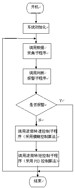
[0020] The combine harvester control device and control method of the present invention will be further described below in conjunction with the accompanying drawings and specific embodiments.

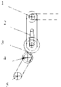
[0021] Please refer to figure 1 As shown, the combine harvester control device of the present invention includes a powered engine 1, a first transmission, a running mechanism, a second transmission and a transmission belt, and the output shaft of the engine 1 drives the wheel shaft 4 through the first transmission and the running mechanism Connected, the driving wheel shaft 4 of the traveling mechanism is connected with the driving wheel shaft 5 of the transmission belt through the second transmission device, the first transmission device includes a transmission belt and a governor for adjusting the forward speed of the traveling mechanism, and the governor includes a hydraulic continuously variable transmission 2 and gearbox 3, the output shaft of the engine 1 transmits power to the dr...


PUM


Abstract

The invention discloses a combine harvester control device and method. The combine harvester control device comprises a load feedback control device, an engine for supplying power, a first transmission device, a walking mechanism, a second transmission device and a transmission band, wherein an output shaft of the engine is connected with a driving sprocket axle of the walking mechanism through the first transmission device. The combine harvester control device is characterized in that the driving sprocket axle of the walking mechanism is connected with a drive sprocket axle of the transmission band through the second transmission device; the load feedback control device comprises a fuzzy control module, a PID (Proportion Integration Differentiation) control module, a first detection element for detecting the rotating speed of a threshing cylinder, and a second detection element for detecting the load torque of the threshing cylinder; the fuzzy control module forms a roller rotating speed control loop by virtue of the first detection element; and the PID control module forms a roller load torque control loop by virtue of the second detection element. According to the invention, on the basis of the conventional combine harvester, the combine harvester control device allows the power of the transmission band of a combine harvester is transmitted by the walking mechanism, and a pure lag link of the conventional transmission band is eliminated, thereby improving control performance greatly. Meanwhile, the roller load torque control loop is formed by the detection on the load torque of the threshing roller, thereby improving the dynamic performance of a roller rotating speed control system, and further improving the work state stability and the harvesting efficiency of the combine harvester.

Description

[0001] technical field [0002] The invention relates to the field of agricultural machinery, in particular to a combine harvester control device and control method. [0003] Background technique [0004] At present, combine harvesters are developing towards automation and high efficiency. The harvesting efficiency of the combine harvester is related to its operating load, and the fluctuation of the operating load directly affects the working state stability and harvesting efficiency of the combine harvester. If the driving speed is too fast, the threshing drum will be overloaded due to the excessive feeding amount, the speed of the threshing drum will drop and the threshing quality will be reduced, and even the threshing drum and the grain conveying auger will be blocked, resulting in shutdown failure; Therefore, it is required to adjust the load in real time when the combine harvester is working, so that the combine harvester can work with high quality and high efficienc...

Claims


Application Information

Patent Timeline
Patent Type & Authority Applications(China)
IPC IPC(8): A01D41/127
Inventor 赵德安李菊秦云张军
Owner 江苏大学扬州(江都)新能源汽车产业研究所
Why Eureka
Try Eureka