

Auxiliary material pushing device of fixed-material cutting machine
A pusher device and cutting machine technology, applied in metal processing, etc., can solve the problems of increased manufacturing costs, uneconomic benefits, waste of materials, etc.
- Summary
- Abstract
- Description
- Claims
- Application Information
AI Technical Summary
Problems solved by technology
Method used
Image

Examples
Embodiment Construction
[0027] Embodiments of the present invention will be described in detail below with reference to the accompanying drawings.
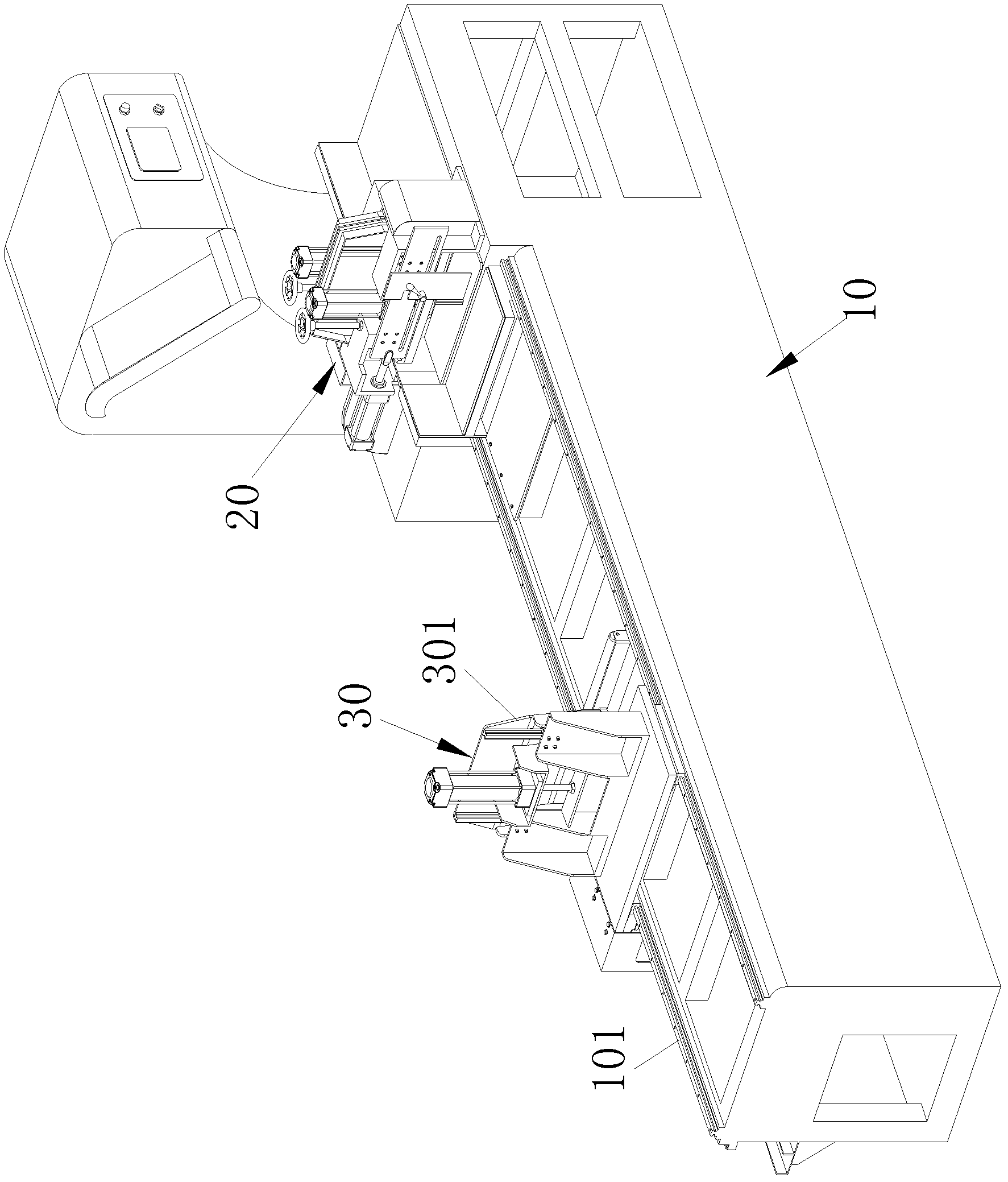
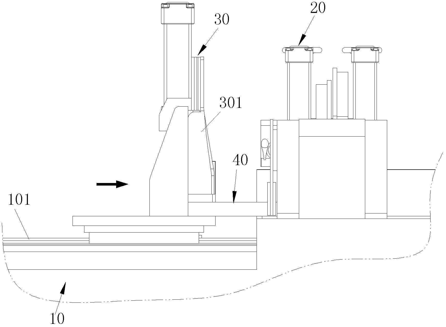
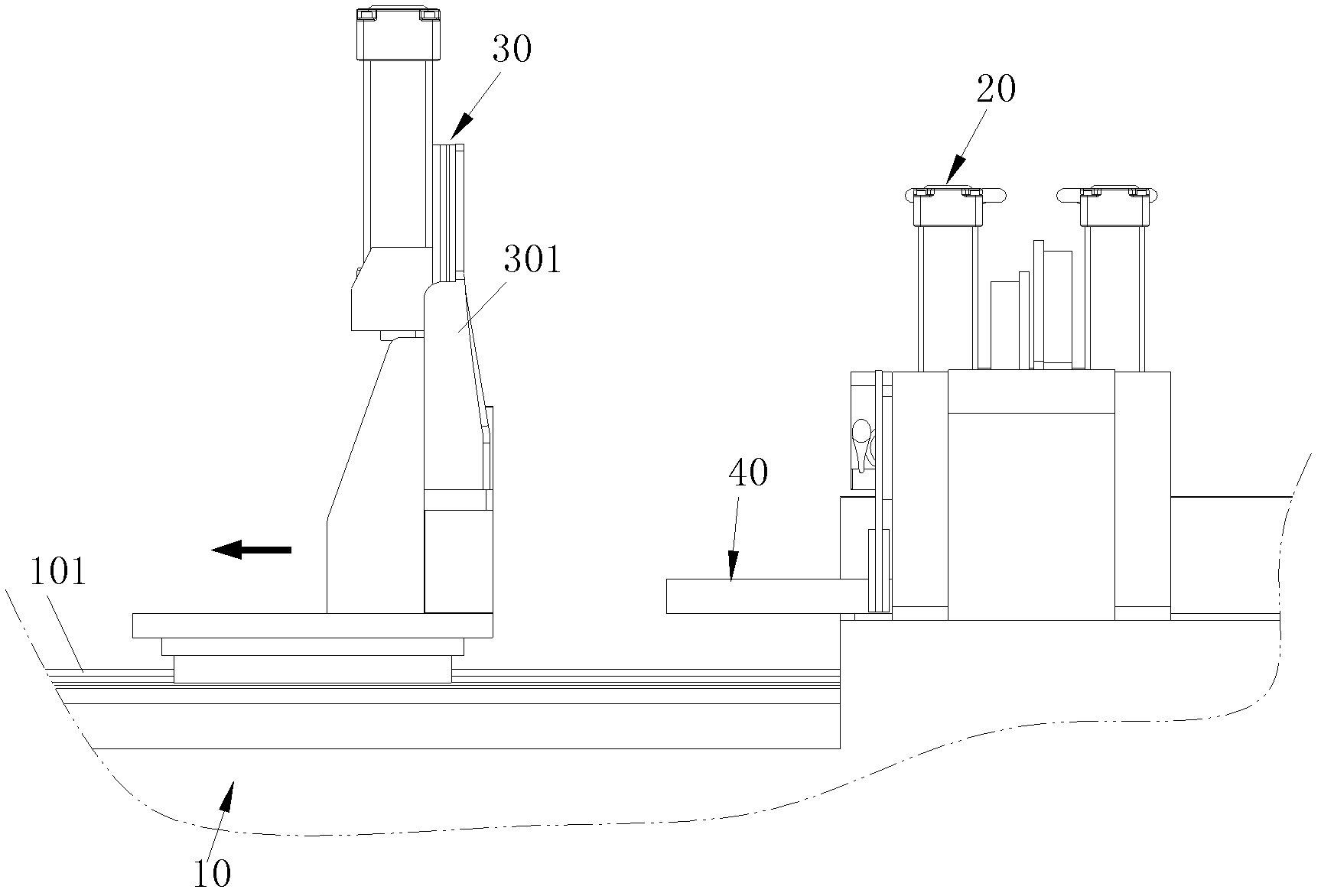
[0028] Such as Figure 4 The schematic diagram of the three-dimensional structure of the fixed material cutting machine using the auxiliary material pushing device of the fixed material cutting machine of the present invention, Figure 5 The feeding device of the auxiliary pushing device of the fixed material cutting machine of the present invention and the schematic diagram of the three-dimensional structure of the auxiliary pushing device and Image 6 As shown in the schematic diagram of the three-dimensional structure of the feeding device of the auxiliary pushing device of the fixed-material cutting machine of the present invention and the other direction of the auxiliary pushing device, the fixed-material cutting machine using the auxiliary pushing device of the fixed-material cutting machine of the present invention includes There is a machine pla...
PUM
 Abstract
Description
Claims
Application Information