
A new type of winding and cutting knife device

A kind of cutting knife, a new type of technology, applied in the direction of winding strip, transportation and packaging, thin material processing, etc., can solve the problems of large up and down swing range, large equipment vibration, long tail material, etc., and achieve small swing range and film tension. The effect of small fluctuation and shortening of tailings

Active Publication Date: 2017-10-17
ZHONGSHAN SOTECH PRINTING MACHINERY CO LTD
View PDF8 Cites 0 Cited by
  • Summary
  • Abstract
  • Description
  • Claims
  • Application Information

AI Technical Summary

Problems solved by technology

[0002] In the printing machine, since each roll of printing material has a certain length, it needs to be cut and received at the rewinding device during continuous printing. The traditional cutting knife adopts a large swing arm to cut and cut, and the range of swinging up and down is large. Shut down to pick up materials, the equipment vibrates greatly, it is easy to wrinkle, and its tailings are long, resulting in a large waste

Method used


Image

  • A new type of winding and cutting knife device
  • A new type of winding and cutting knife device
  • A new type of winding and cutting knife device

Examples


Embodiment Construction

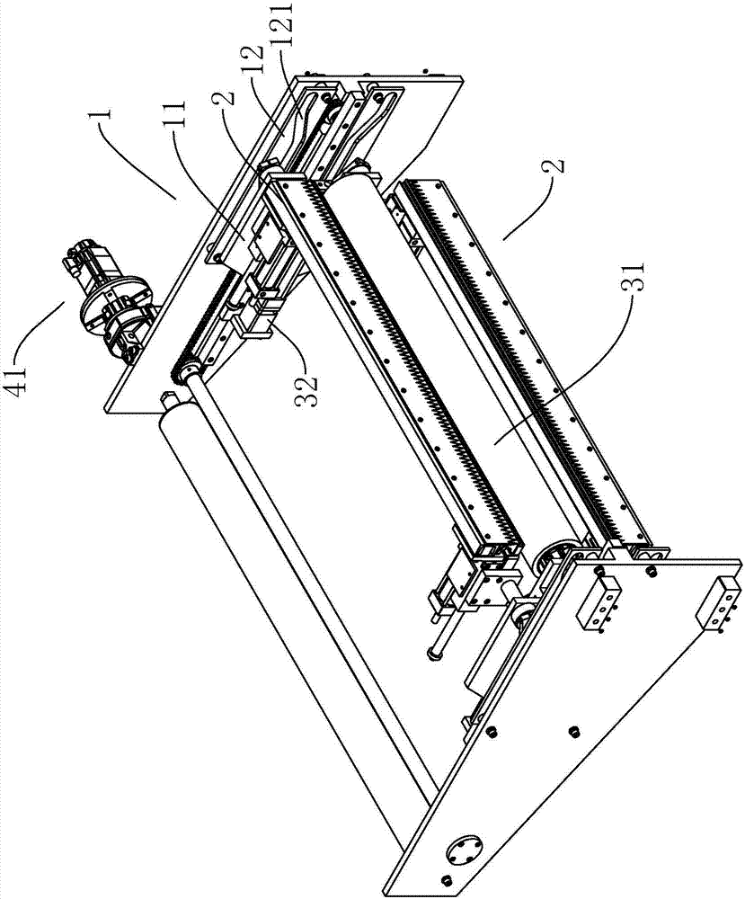
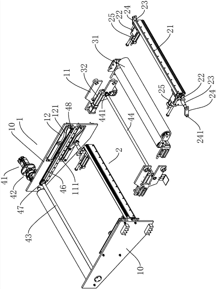
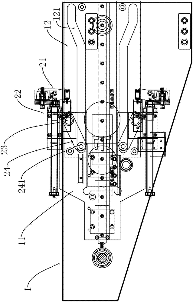
[0018] refer to Figure 1 to Figure 3 , Figure 1 to Figure 3 It is a structural schematic diagram of a specific embodiment of the present invention. As shown in the figure, a new type of winding cutter device includes a frame 1, a flat push roller device, and a cutter assembly. The two sides of the frame 1 pass a translation The drive devices are respectively provided with moving plates 11. Preferably, in this embodiment, the frame 1 includes two sets of oppositely arranged base plates 10, the translation drive device is a sprocket drive device, and the sprocket drive device Including a motor 41, a reducer 42, and a transmission shaft 43, the two ends of the transmission shaft 43 are respectively rotated and arranged on the base plate 10, the motor 41 is fixed on the frame 1 and connected to the transmission shaft 43 through the reducer 42, the The transmission shaft 43 is located at one end of the base plate 10 and the two ends of the transmission shaft 43 are respectively ...


PUM


Abstract

The invention discloses a novel winding cutting knife device. The novel winding cutting knife device comprises a machine frame, a flat pushing pressing roller device, and a cutting knife assembly, wherein moving plates are arranged on two sides of the machine frame; the flat pushing pressing roller device and the cutting knife assembly are arranged on the moving plates; the cutting knife assembly comprises two groups of cutting knife mechanisms which are oppositely arranged above the flat pushing pressing roller device and under the flat pushing pressing roller device; each of the cutting knife mechanism comprises a cutting knife and cutting knife bases positioned at two ends of the cutting knife; a pushing mechanism is arranged on the cutting knife bases; two groups of guiding plates corresponding with the cutting knife mechanisms are arranged on the machine frame, and are oppositely arranged. When a printing material needs to be cut, the moving plates are moved forward; the guiding plates guide the cutting knife bases and the cutting knives to rotate around a rotating shaft; the cutting knives of the two groups of the cutting knife mechanisms relatively rotate in a closing manner; the flat pushing pressing roller device is in contact with an air bulking shaft; the two groups of the cutting knives are relatively oblique and close to the printing material, and then the two groups of the cutting knifes are pushed to move forward and fit cut, so that the printing material can be cut off. According to the novel cutting knife device disclosed by the invention, the swinging range of each of the cutting knifes is small, tail materials are shortened, the waste is reduced, besides, the cutting knifes stably move, the positioning accuracy is high, the tensile force fluctuation of a film is small, and the printing material is not liable to wrinkle.

Description

technical field [0001] The invention relates to the field of printing machines, in particular to a novel winding cutter device. Background technique [0002] In the printing machine, since each roll of printing material has a certain length, it needs to be cut and received at the rewinding device during continuous printing. The traditional cutting knife uses a large swing arm to cut and cut, and the range of swinging up and down is large. Stopping to pick up materials, the equipment vibrates greatly, is easy to wrinkle, and its tailings are long, resulting in large waste. Contents of the invention [0003] In order to overcome the deficiencies of the prior art, the invention provides a novel winding cutter device. [0004] The technical solution adopted by the present invention to solve its technical problems is: [0005] A new type of rewinding and cutting knife device, including a frame, a flat push roller device, and a cutter assembly. Moving plates are respectively a...

Claims


Application Information

Patent Timeline
Patent Type & Authority Patents(China)
IPC IPC(8): B65H19/26
CPCB65H19/26B65H2601/25
Inventor 郭景松孟宗发吴文秋黄亚东
Owner ZHONGSHAN SOTECH PRINTING MACHINERY CO LTD
Learn More