Roller bed conveying device

A technology of conveying device and roller table, which is applied in the direction of roller table, transportation and packaging, etc. It can solve the problems of complex installation, high manufacturing cost, processing and complicated structure of roller table bracket, and achieve the effect of stable operation and simple structure

Inactive Publication Date: 2013-02-20
WUXI HUALIAN PRECISION MACHINERY
View PDF5 Cites 12 Cited by
  • Summary
  • Abstract
  • Description
  • Claims
  • Application Information

AI Technical Summary

Problems solved by technology

In the prior art, the roller table conveying device of the steel plate processing line usually adopts the lifting roller table to realize the active and passive switching of the roller table. This method has high manufacturing cost and complicated installation; The practice of active and passive switching of the roller table, but the arrangement of the clutch is usually arranged on the roller table support for transition, and the processing and structure of the roller table support are also relatively complicated.

Method used


Image

  • Roller bed conveying device
  • Roller bed conveying device
  • Roller bed conveying device

Examples


Embodiment Construction

[0015] The specific implementation manner of the present invention will be described below in conjunction with the accompanying drawings.

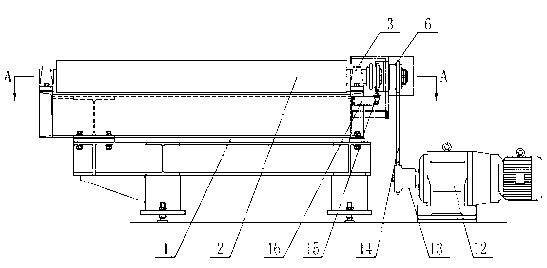
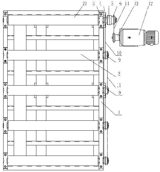
[0016] See figure 1 , the present invention comprises a frame 1, a roller 2 and a geared motor 12 outside the frame 1, and the two ends of the roller 2 are mounted on the frame 1 through bearing blocks 3; see figure 2 , image 3 , the shaft end on one side of the first roller 21 is sequentially connected with the first sprocket 4 and the electromagnetic clutch 5 through a key connection, the electromagnetic clutch 5 adopts a jaw type electromagnetic clutch, and the second sprocket 6 is mounted on the first sprocket through a bearing 7. The shaft end on one side of the roller 21 is locked by a round nut 8, the second sprocket 6 is connected to the clutch end of the electromagnetic clutch 5, and the lower end of the electromagnetic clutch 5 is in contact with the electric brush 15, and the electric brush 15 is installed on the fixed frame ...


PUM


Abstract

A roller bed conveying device comprises a frame, rollers and a reduction motor arranged outside the frame. Two ends of the rollers are arranged on the frame through bearing seats. A first chain wheel, an electromagnetic clutch and a second chain wheel are sequentially connected onto a shaft end on one side of a first roller. The second chain wheel is arranged on the shaft end on one side of the first roller through a bearing, locked through a round nut and connected with a clutch end of the electromagnetic clutch. Third chain wheels are connected to a shaft end on one side of another roller. The first chain wheel is connected with the third chain wheels through first chains, and two adjacent third chain wheels are connected through a second chain. An output shaft of the reduction motor is connected with a transmission chain wheel which is connected with the second chain wheel through a third chain. By means of the roller bed conveying device, active and passive transformation of a roller bed can be convenient. In addition, the roller bed conveying device is simple in structure and reliable in operation.

Description

technical field [0001] The invention relates to a device for conveying materials, in particular to a roller table conveying device used in a steel plate processing production line. Background technique [0002] The steel plate processing production line is mainly used for punching, drilling, milling, cutting and other processing of the steel plate, and the conveying work of the steel plate is usually completed by the feeding and conveying device installed on the entire production line. The feeding and conveying device usually adopts roller Road conveying device. In the prior art, the roller table conveying device of the steel plate processing line usually adopts the lifting roller table to realize the active and passive switching of the roller table. This method has high manufacturing cost and complicated installation; The practice of active and passive switching of the roller table, but the arrangement of the clutch is usually arranged on the roller table support for trans...

Claims


Application Information

Patent Timeline
Patent Type & Authority Applications(China)
IPC IPC(8): B65G13/07
Inventor 董立锋邵燕瑛
Owner WUXI HUALIAN PRECISION MACHINERY
Why Eureka
Try Eureka