Feedstock tensioning mechanism for garment tailoring equipment

A tensioning mechanism and equipment technology, applied in the field of garment machinery, can solve the problems of reduced production efficiency, non-conforming fabrics, inaccurate blanking of fabrics, etc., to achieve the effects of reduced production efficiency, avoidance of cutting errors, and stable processing quality

Inactive Publication Date: 2014-10-15
佛山市顺德区爱斯达科技研发有限公司
View PDF5 Cites 6 Cited by
  • Summary
  • Abstract
  • Description
  • Claims
  • Application Information

AI Technical Summary

Problems solved by technology

In the process of fabric processing, the laser cutting machine needs to pre-spread the whole roll of cloth before cutting. In the past, the cloth feeding device used in the cloth spreading process is driven by a motor, and the cloth falls directly on the workbench. On the other hand, there is no pre-tensioning, so that the cloth falling on the workbench is easy to wrinkle, and the blanking of the cloth is very inaccurate, and the cloth is often not within the laser cutting range of the laser cutting machine, so that the cutting of the laser cutting machine is not accurate. Rules, irregularity, waste of fabric, and the cut fabric does not meet the specifications, resulting in a reduction in the production efficiency of the enterprise

Method used


Image

  • Feedstock tensioning mechanism for garment tailoring equipment
  • Feedstock tensioning mechanism for garment tailoring equipment
  • Feedstock tensioning mechanism for garment tailoring equipment

Examples


Embodiment 1

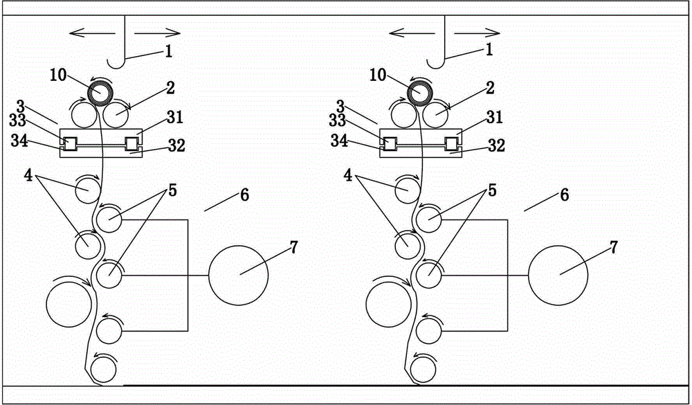
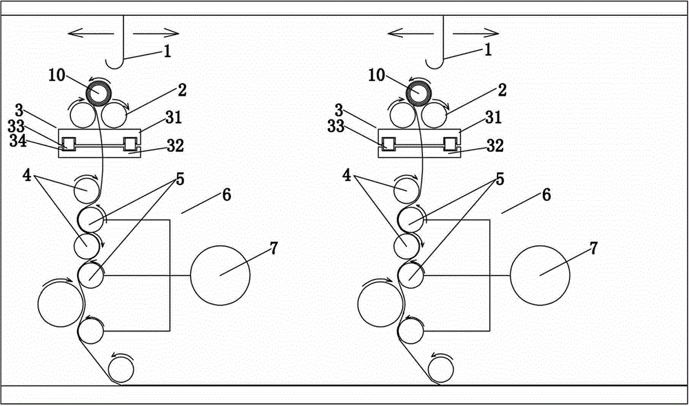
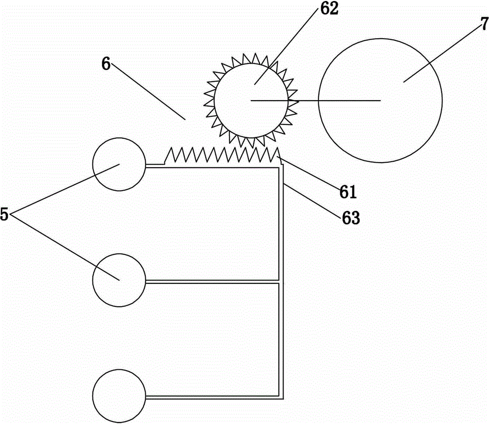
[0019] Example 1, such as Figure 1 to Figure 4 As shown, a garment cutting device includes a feeding tension mechanism, and the feeding tension mechanism includes a mounting base 3, two feed rollers 2 arranged side by side on the mounting base, and three parallel and horizontal tensioning rollers. The tension roller 5, two feed rollers 4 that are parallel to each other and arranged horizontally, and the driving assembly 6 that drives the tension roller 5 to move laterally so that the tension roller 5 and the feed roller 4 are vertically staggered. The two feeding rollers 2 rotate in the same direction and are separated from each other. The feeding roller 4 is arranged below the mounting seat, and the tension roller 5 is arranged on one side of the feeding roller 4. The tension roller 5 and the feeding roller 4 are adjacent in pairs, parallel to each other, and rotate in opposite directions. Of course, in order to increase or decrease the tension of the cloth so that the clot...


PUM


Abstract

The invention relates to the technical field of garment machinery, in particular to a feedstock tensioning mechanism for garment tailoring equipment. The feedstock tensioning mechanism comprises a mounting seat, two feeding rolls, at least two tensioning rolls, at least two conveying rolls and a driving subassembly, wherein the two feeding rolls are arranged on the mounting seat side by side; the tensioning rolls are parallel to one another and are horizontally arranged; the conveying rolls are parallel to one another and are horizontally arranged; the driving subassembly drives the tensioning rolls to move transversely so that the tensioning rolls and the conveying rolls are staggered in the vertical direction; the two feeding rolls rotate in the same direction and are separated from each other; the conveying rolls are arranged below the mounting seat; each tensioning roll is arranged on one side of the corresponding conveying roll; the tensioning rolls and the conveying rolls are adjacent in pairs; and each tensioning roll and the corresponding conveying roll are parallel to each other, and rotate reversely. The tensioning rolls and the conveying rolls are parallel to each other and are staggered, and problems that tailoring equipment tailors cloth mistakenly due to the fact that the cloth has wrinkles, the tailored cloth does not meet specifications, the cloth is wasted, and the production efficiency of an enterprise is reduced are effectively solved.

Description

technical field [0001] The invention relates to the technical field of garment machinery, in particular to a feeding tensioning mechanism for garment cutting equipment. Background technique [0002] Existing laser cutting equipment is widely used in the clothing and bag industries, for cutting textiles, such as laser cutting machines. In the process of fabric processing, the laser cutting machine needs to pre-spread the whole roll of cloth before cutting. In the past, the cloth feeding device used in the cloth spreading process is driven by a motor, and the cloth falls directly on the workbench. On the other hand, there is no pre-tensioning, so that the cloth falling on the workbench is easy to wrinkle, and the blanking of the cloth is very inaccurate, and the cloth is often not within the laser cutting range of the laser cutting machine, so that the cutting of the laser cutting machine is not accurate. Rules, irregularities, waste of fabric, and the cut fabric does not mee...

Claims


Application Information

Patent Timeline
Patent Type & Authority Applications(China)
IPC IPC(8): D06H7/22
Inventor 樊友斌
Owner 佛山市顺德区爱斯达科技研发有限公司
Why Eureka
Try Eureka