Valve for use in a container which employs pressure to dispense product

a technology of valves and containers, which is applied in the direction of liquid transferring devices, instruments, volume meters, etc., can solve the problems of difficulty for users to maintain a steady flow of products, and achieve the effect of disabling the valve and minimizing the risk of having

Active Publication Date: 2012-07-03
GUY CHEM CO LLC
View PDF34 Cites 9 Cited by
  • Summary
  • Abstract
  • Description
  • Claims
  • Application Information

AI Technical Summary

Benefits of technology

[0024]The dispensing openings in the stem are elongate in the axial direction to facilitate control over exposing only a proportion of the opening. The openings preferably have an inverted triangular shape and thus provide a more sensitive control over the effective opening as the stem is depressed.
[0026]Recesses in the edge of the button allow product to travel past the edge of the button to reach the valve stem sidewall openings when the valve is open. The recesses in the button are at least equal in area to the valve stem openings so as to avoid further restriction on the flow of the product to be dispensed.
[0028]To minimize the risk of having the foot snap over the shoulder and thus disable the valve, it is important that the flange provided by the foot is fully inserted in the recess on stem wall. To assure this full engagement, the inner diameter of the boot below the foot flange has a slight interference relationship with the stem wall.

Problems solved by technology

A major reasons why compressed nitrogen or air is not used is that the pressure decrease as product is dispensed makes it difficult for the user to maintain a steady flow of product.

Method used


Image

  • Valve for use in a container which employs pressure to dispense product
  • Valve for use in a container which employs pressure to dispense product
  • Valve for use in a container which employs pressure to dispense product

Examples


Embodiment Construction

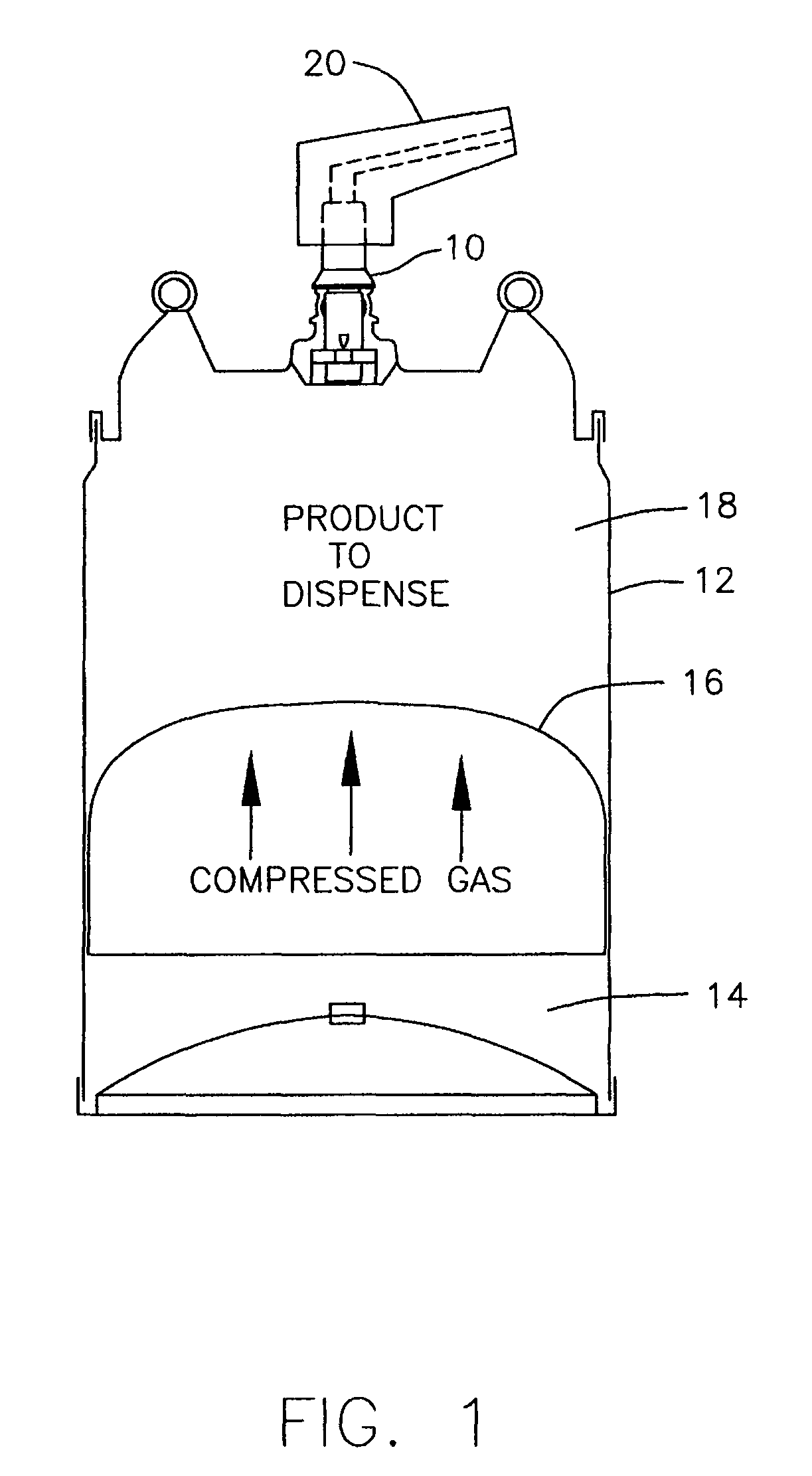
[0045]The FIGS. essentially illustrate a single embodiment. FIG. 1 is a schematic illustration of the assembly of the valve 10 and the container 12. The compressed gas propellant 14 is below the piston 16 and the product to be dispensed 18 is above the piston 16. A combined actuator and nozzle 20 is mounted on the valve 10.

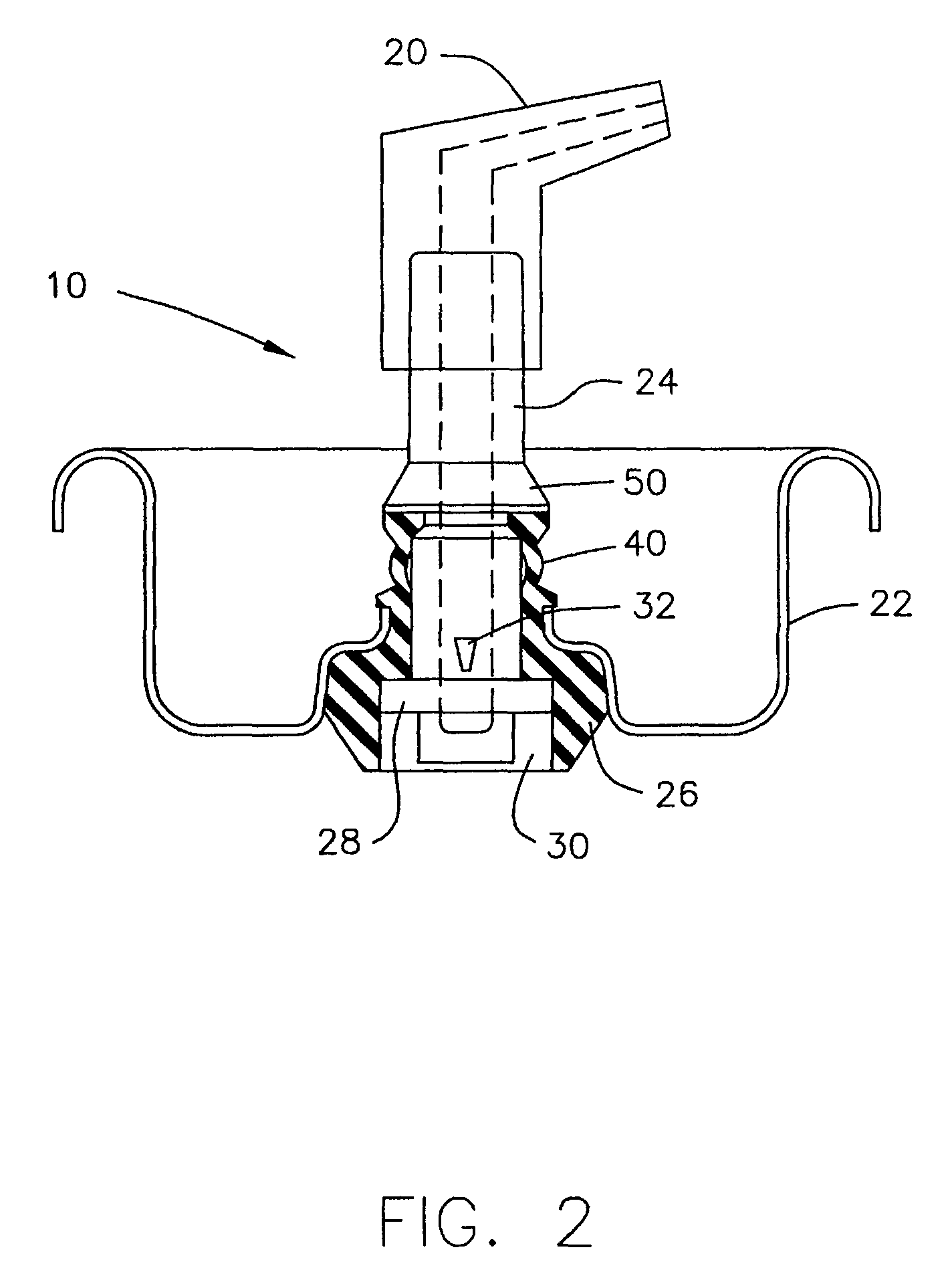
[0046]As shown in FIG. 2, the valve 10 is a three piece valve assembly. It is constituted by a mounting cup 22, a movable valve element 24 and a resilient annular sealing grommet 26. The movable valve element 24 is also referred to as a valve stem 24. Both stem 24 and grommet 26 have a vertical axis and respective vertical bores 52 and 56.

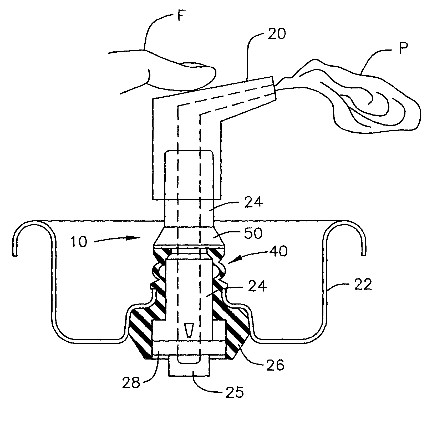
[0047]With reference to FIGS. 2 and 3, the finger F operated actuator 20 is used to move the valve from a FIG. 2 closed state to its FIG. 3 open state. In the open state, product P is dispensed because of the pressure within the container to which the valve is mounted.

[0048]A lower portion of stem 24 has a button 28 which fits in...


PUM


Abstract

A valve for a pressurized dispensing container has a resilient annular grommet that surrounds a valve stem. The grommet has a lower segment which engages an elongate valve stem opening with a slight interference fit to provide user controllable metering of the product being dispensed. A recess in the lower surface of the grommet contains the stem button from the closed state to the fully open state to provide stability for the stem. The upper portion of the grommet has a restoring boot to assure that the valve is returned to its closed state once manual force is removed from the valve. A boot flange and stem recess engagement together with other dimensional relationships assures that the boot provide the required restoring force throughout the dispensing of product.

Description

REFERENCE TO RELATED APPLICATIONS[0001]This application is a continuation-in-part of Ser. No. 12 / 009,518 filed 18 Jan. 2008 which is a continuation-in-part of Ser. No. 11 / 842,632 filed 21 Aug. 2007 and Ser. No. 11 / 842,640 filed 21 Aug. 2007; which applications in turn are continuations-in-part of Ser. No. 11 / 334,716 filed 18 Jan. 2006, which in turn is a continuation-in-part of Ser. No. 10 / 882,625 filed 30 Jun. 2004 now abandoned, which in turn is a continuation of Ser. No. 10 / 816,969 filed 2 Apr. 2004, now abandoned, and which in turn is a continuation of Ser. No. 10 / 285,238 filed 31 Oct. 2002, now abandoned; the entire disclosures of which are hereby incorporated by reference.BACKGROUND OF THE INVENTIONBackground and Objects[0002]Vast numbers of hand held pressurized containers for dispensing products such as gel shave are used by consumers and industry. Normally a finger or lever actuated valve is used to permit dispensing product from a nozzle on the top of the container. A hydr...

Claims


Application Information

Patent Timeline
Patent Type & Authority Patents(United States)
IPC IPC(8): B65D83/00
CPCB65D83/48
Inventor SCHEINDEL, CHRISTIAN T.
Owner GUY CHEM CO LLC
Why Eureka
Try Eureka