Composite pipe concrete composite structure

A combined structure and concrete technology, applied in the direction of columns, piers, pillars, etc., can solve problems such as high yield load, and achieve the effect of high yield load, increased bearing capacity, and increased yield load.

Inactive Publication Date: 2015-06-03
NANJING FORESTRY UNIV +2
View PDF5 Cites 0 Cited by
  • Summary
  • Abstract
  • Description
  • Claims
  • Application Information

AI Technical Summary

Problems solved by technology

[0005] The purpose of the present invention is to provide a composite tubular concrete composite structure, in order to solve the defects of the existing steel tubular concrete structure, FRP-steel composite tubular concrete structure, so that the structure has a higher yield load, sufficient bearing capacity reserve, ductility and relaxation damage mode

Method used


Image

  • Composite pipe concrete composite structure
  • Composite pipe concrete composite structure
  • Composite pipe concrete composite structure

Examples


Embodiment 1

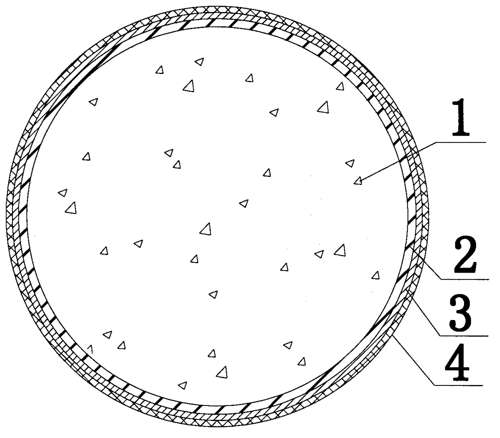
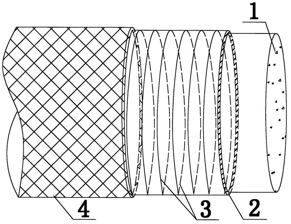
[0035] Such as figure 1 , figure 2 , a composite tubular concrete composite structure, comprising internal concrete 1, steel pipe 2, transverse prestressed steel wire 3, and fiber-reinforced plastic 4; wherein, the transverse prestressed steel wire 3 is continuously and uniformly wound on the outer wall of the steel pipe 2 by applying prestress to the steel wire , the fiber reinforced plastic 4 is pasted on the outer surface of the transverse prestressed steel wire 3, the internal concrete 1 is filled in the interior of the steel pipe 2, and the transverse prestressed steel wire 3 and the fiber reinforced plastic 4 are each one layer.

Embodiment 2

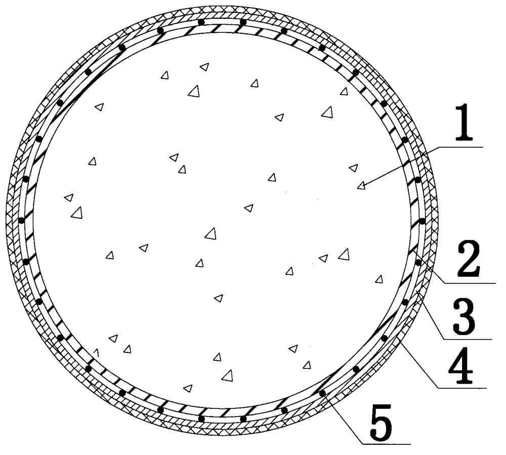
[0037] Such as image 3 , Figure 4 , a composite tubular concrete composite structure, comprising internal concrete 1, steel pipes 2, transverse prestressed steel wires 3, fiber reinforced plastics 4, and longitudinal steel wires 5; wherein, the transverse prestressed steel wires 3 are wound horizontally and uniformly by applying prestress to the steel wires On the outer wall of the steel pipe 2, the fiber reinforced plastic 4 is pasted on the outer surface of the transverse prestressed steel wire 3, and the internal concrete 1 is filled in the interior of the steel pipe 2, and the transverse prestressed steel wire 3 and the fiber reinforced plastic 4 are each one layer. At the same time, a layer of longitudinal steel wires 5 is arranged between the transverse prestressed steel wires 3 and the steel pipe 2. During specific implementation, the longitudinal steel wires 5 are evenly arranged around the steel pipe 2 along the axial direction of the steel pipe 2, and are temporari...

Embodiment 3

[0039] Such as Figure 5 , Figure 6 , a composite tubular concrete composite structure, comprising internal concrete 1, steel pipes 2, transverse prestressed steel wires 3, fiber reinforced plastics 4, and longitudinal steel wires 5; wherein, the transverse prestressed steel wires 3 are wound horizontally and uniformly by applying prestress to the steel wires On the outer wall of the steel pipe 2, the fiber reinforced plastic 4 is pasted on the outer surface of the transverse prestressed steel wire 3, and the internal concrete 1 is filled in the interior of the steel pipe 2. The transverse prestressed steel wire 3 has two layers, and the winding distances of the two layers are different. The fiber reinforced plastic 4 is 1 layer. At the same time, between the transverse prestressing steel wire 3 and the steel pipe 2 and between the two layers of transverse prestressing steel wire 3, a layer of longitudinal steel wire 5 is respectively arranged. During specific implementation...


PUM

PropertyMeasurementUnit
tensile strengthaaaaaaaaaa
diameteraaaaaaaaaa

Abstract

The invention relates to a composite pipe concrete composite structure which is characterized in that the structure comprises internal concrete (1), a steel pipe (2), transverse pre-stressed steel wires (3), and a fiber-reinforced plastic material (4). According to the invention, through applying pre-stress to the steel wires, the pre-stressed steel wires (3) are transversally continuously and uniformly wound on the outer wall of the steel pipe (2). The fiber-reinforced plastic material (4) is adhered to the outer surface of the transverse pre-stressed steel wires (3) on the outer layer. The internal concrete (1) is filled in the steel pipe (2). The winding pitches between the transverse pre-stressed steel wires (3) are no larger than 40mm. With the structure provided by the invention, defects of commonly known steel pipe concrete and FRP-steel composite pipe concrete structures are overcome, and advantages such as high yield load, large bearing capacity storage, good ductility, moderate failure mode, good durability, and the like are provided. Especially, the structure has stable and continuous decline stage and low cost. The structure provide by the invention is suitable to be used in piles, columns, bridge piers, and arch ribs in newly built structures, and can be used in reinforcement of mainly compressed members in existing reinforced concrete structures and steel pipe concrete structures.

Description

technical field [0001] The invention relates to a concrete structure, in particular to a composite tube-concrete combined structure, which belongs to the technical field of civil engineering structures. Background technique [0002] Over the years, scholars at home and abroad have conducted a lot of research and application on the steel tube concrete structure, which has the advantages of good seismic performance and convenient construction. At the same time, it is also recognized that the steel tube concrete structure has the following defects and shortcomings: The vertical stress generated by the load must also bear the shear force and the lateral stress generated by the expansion of the concrete. The two-way stress state will reduce the confinement effect of the steel pipe and advance the local buckling of the steel pipe. The low-cycle repeated load test shows that this local buckling will lead to abnormal Stable hysteretic cycle reduces the ductility of components, and t...

Claims


Application Information

Patent Timeline
Patent Type & Authority Patents(China)
IPC IPC(8): E04C3/34
Inventor 魏洋吴刚吴智深蒋剑彪张敏
Owner NANJING FORESTRY UNIV
Why Eureka
Try Eureka