Integrated hydro-pneumatic spring device

An oil-pneumatic spring and integrated technology, which is applied in the direction of spring, spring/shock absorber, shock absorber-spring combination, etc., can solve problems such as the limitation of the application of electromechanical simulation theory, improve driving comfort and handling stability, and improve Suspension sprung mass, effect of reducing confinement

Inactive Publication Date: 2013-02-20
JIANGSU UNIV
View PDF7 Cites 17 Cited by
  • Summary
  • Abstract
  • Description
  • Claims
  • Application Information

AI Technical Summary

Problems solved by technology

Therefore, the application of electromechanical

Method used


Image

  • Integrated hydro-pneumatic spring device

Examples


Embodiment Construction

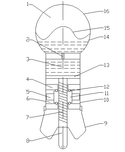
[0029] figure 1Shown is an integrated oil-gas spring device, including an inerter working part, a damping working part, and an outer protection part. The outer protection part includes a protective cover 9 and a working cylinder 10, and the lower end of the working cylinder 10 is fixed with the protective cover 9 through a sealing structure; The working part of the inerter includes a piston 13, an upper limit ring 4, a lower limit ring, a flywheel 5 and a ball screw structure 7. The ball screw structure 7 includes a piston rod 8, a ball screw nut 11 and a ball 12. The piston rod 8 passes through the ball The screw nut 11, and the ball screw nut 11 and the screw rod part of the piston rod 8 are screw fit, the contact surface between the ball screw nut 11 and the upper limit ring 4 and the lower limit ring is provided with a ball ring groove, and the balls 12 is placed in the ball ring groove, the flywheel 5 is coaxially fixed on the ball screw nut 11, the piston 13 is fixed on ...


PUM


Abstract

The invention discloses an integrated hydro-pneumatic spring device. An inerter working chamber is coaxially arranged in a damping working cylinder, a piston portion in the inerter working chamber is arranged as a screw rod structure, a ball screw nut is arranged on the screw rod in the inerter working chamber according to a ball screw principle, a flywheel is coaxially fixed on the ball screw nut, the nut is limited in the middle section and can only rotate around the screw rod through two stop collars fixed at the top and bottom of the working cylinder, and ball circular grooves are arranged on contact surfaces of the stop collars with the nut. As an improvement, self-weight of a vehicle body is not increased when sprung mass of a suspension is improved, driving comfort and handling stability of vehicles are improved, complex mechanical network combined process is avoided, and spatial arrangement limitation is reduced due to coaxial parallel connection of the inerter and the damping.

Description

technical field [0001] The invention relates to an oil-pneumatic spring device, in particular to an integrated oil-pneumatic spring device in which an inerter and a damper are coaxially connected in parallel. Background technique [0002] 1. Electromechanical simulation theory: [0003] At present, mechatronics has become an important development direction in the field of engineering in the new century. In this integration process, it is often necessary to network the mechanical and electronic systems as a large system for research. [0004] According to the characteristic that the mathematical model of the mechanical system and the corresponding circuit system under the condition of simple harmonic excitation, that is, the differential equation or transfer function describing their dynamic characteristics, has the same form, two different electromechanical simulation theories have been proposed in history. One is "force-voltage" correspondence, that is, mass, damping, and...

Claims


Application Information

Patent Timeline
IPC IPC(8): F16F13/00
Inventor 陈龙杨晓峰沈钰杰汪若尘
Owner JIANGSU UNIV
Why Eureka
Try Eureka