Device for measuring pipe ovality

A technology for measuring the ellipticity of pipes, applied in the direction of mechanical counter/curvature measurement, etc., which can solve the problems of inaccurate determination of the extreme values ​​of the major axis and minor axis, difficulty in achieving 360-degree rotation, and difficulty in parallelism, etc., to achieve measurement accuracy With economic applicability, easy to read and save, saving manpower and time

Active Publication Date: 2013-02-20
TIANJIN UNIV
View PDF8 Cites 15 Cited by
  • Summary
  • Abstract
  • Description
  • Claims
  • Application Information

AI Technical Summary

Problems solved by technology

Among them, the device for measuring the ovality of pipe fittings by laser method is relatively complicated and expensive, and it is not convenient for rapid measurement at the production or laying site
There are the following problems in the measurement of the device for measuring the ellipticity of pipe fittings by mechanical means: first, the human error factors of the result are difficult to control, such as CN 202158829 U "a portable steel pipe ellipticity measuring instrument" and CN 201780083 U "a kind of measuring steel pipe In the method described in "Measuring tools for extreme diameter and ellipticity", the measuring personnel are required to rotate the measuring device 360 ​​degrees along the outer wall of the pipe fitting. The 360-degree rotation of the restriction measuring device is not easy to realize; second, the determination of the extreme value of the major axis and the minor axis of the section is not accurate enough

Method used


Image

  • Device for measuring pipe ovality
  • Device for measuring pipe ovality
  • Device for measuring pipe ovality

Examples


Embodiment Construction

[0020] The present invention will be described below in conjunction with the accompanying drawings and embodiments.

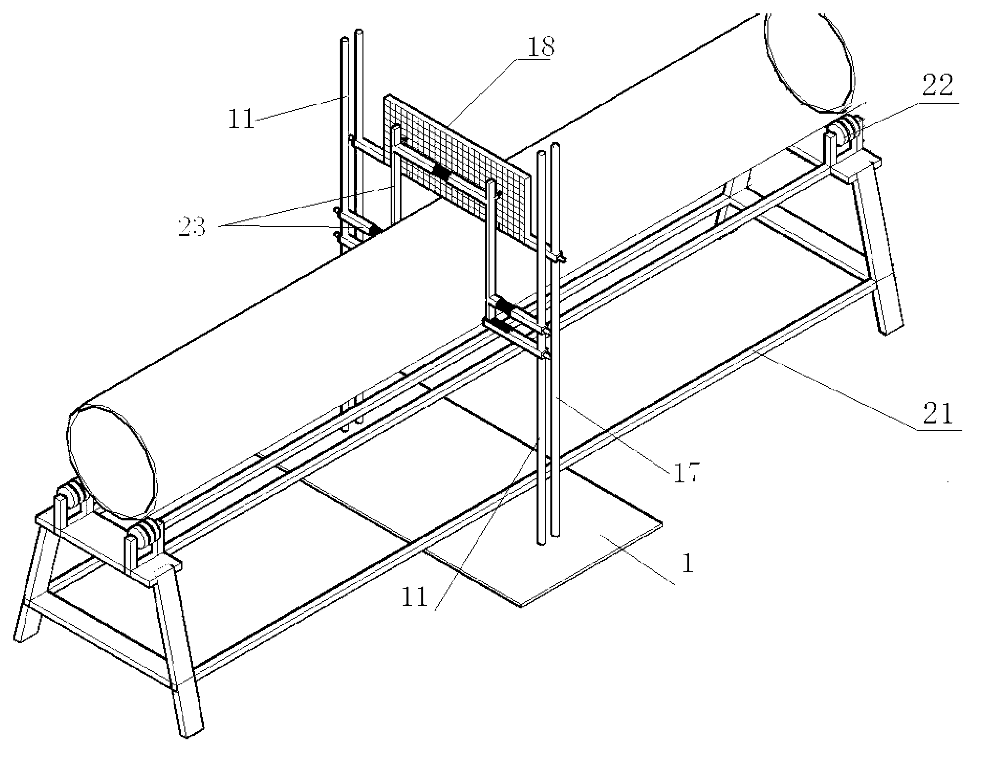
[0021] This embodiment provides a device for measuring the ellipticity of pipelines, the overall structure diagram is as follows figure 1 As shown, the pipe to be tested is placed on a pipe support 21 with rollers 22 . The measuring device mainly includes a drawing board 18 detachably mounted on two drawing board columns 17, an ellipticity measuring mechanism connected to the two measuring columns 11, and a long-axis endpoint calibration mechanism. The profile of the ellipticity measuring mechanism is a "several"-shaped portal frame 23 located on the same plane with left and right symmetry. Two drawing board uprights 17 and two measuring uprights 11 are vertically fixed on the base 1, and the drawing board 18 and " few " glyph frame 23 are parallel to each other. During the measurement, the pipeline to be tested is clamped in the "several" shaped portal frame...


PUM


Abstract

The invention belongs to the technical field of pipe production and laying installation and relates to a device for measuring pipe ovality. The device comprises a drawing board connected onto a drawing board column and an ovality measuring mechanism connected onto a measuring column. The drawing board column and the measuring column are vertically fixed. The ovality measuring mechanism comprises two vertical rods connected through a horizontal beam with a horizontal spring. The lower portion of the ovality measuring mechanism is connected onto the measuring column on the same side through an upper beam and a lower beam respectively. One end of the lower beam is vertically fixed on the measuring column on the same, a guide groove is axially arranged on the upper portion of the other end of the lower beam, and the lower ends of the vertical rods are installed in the guide groove through balls. The upper beam is provided with a demarcation spring, and the upper ends of the two vertical rods are respectively fixedly connected with a marking pen pointing to the drawing board. By means of the device, measurement workers can conveniently and directly read length of a long shaft and a short shaft on the section of a pipe, and simultaneously determines the position of endpoints of the long shaft. The device achieves quality checking of the large-diameter pipe.

Description

technical field [0001] The invention belongs to the technical field of pipeline production, laying and installation, and relates to a pipeline parameter measuring device, which can provide reference for predicting and controlling its working state after laying and operation. Background technique [0002] The submarine oil and gas pipeline is the lifeline project of the country, and its safety is of great importance to my country's offshore oil development and national economic development. However, the marine environmental conditions are complex and diverse. Submarine pipelines are subjected to complex loads and environmental conditions such as self-weight, external hydrostatic pressure, internal pressure, rough seabed, and seawater corrosion. Buckling and buckling propagation, once the submarine pipeline is buckled and damaged, it will lead to extremely serious oil and gas leakage accidents, which will cause huge economic, social, political and ecological losses to the coun...

Claims


Application Information

Patent Timeline
IPC IPC(8): G01B5/20
Inventor 余建星李妍李小龙孙震洲卞雪航杨源梁静
Owner TIANJIN UNIV
Why Eureka
Try Eureka