Projection camera lens
A projection lens and projection technology, applied in the field of projection lenses, can solve the problems of complex structure, high price, difficult control of yield rate, etc., and achieve the effect of high light utilization efficiency, low cost, and large display size
- Summary
- Abstract
- Description
- Claims
- Application Information
AI Technical Summary
Problems solved by technology
Method used
Image
Examples
Embodiment 1
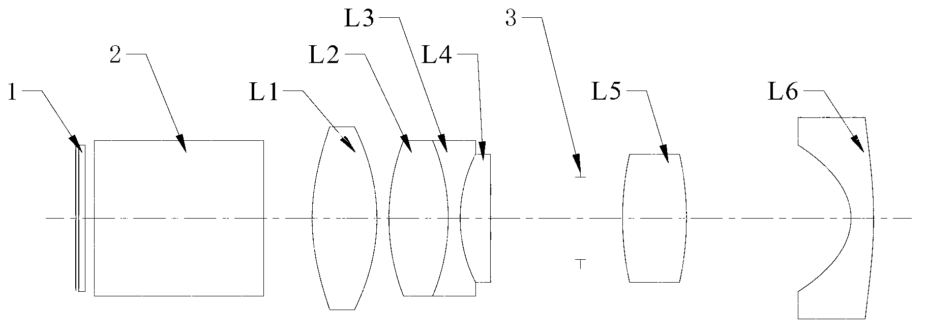
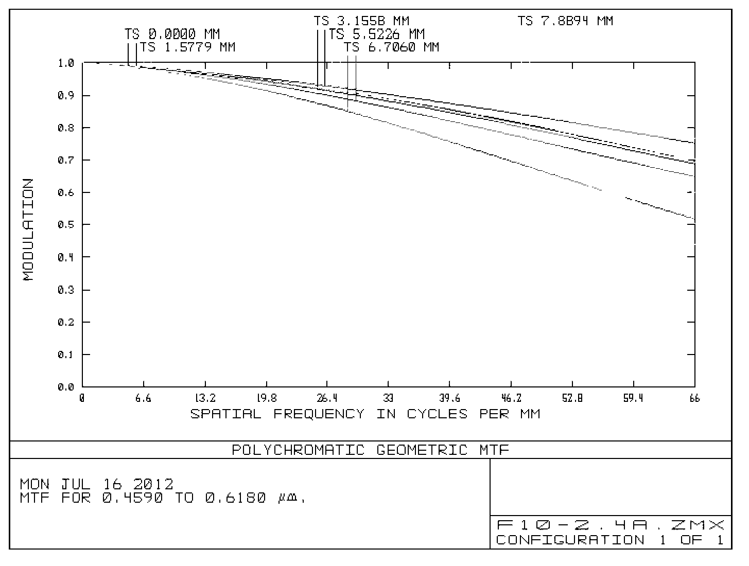
[0060] In the imaging system provided by Embodiment 1 of the present invention, the projection imaging system has a half field of view FOV.=38.38°, the projection imaging system focal length f'=10.0 mm, and the projection imaging system object space NA=0.204. The lens components are arranged sequentially from the light splitting device to the display screen as follows: figure 1 As shown, aspherical biconvex lens [L1]; spherical biconvex lens [L2]; spherical biconvex lens [L3]; spherical plano-convex lens [L4] with a convex surface on the display device side; spherical biconvex lens [L5]; aspheric crescent The lens [L6] has a convex surface on one side of the screen; the spherical biconvex lens [L2], the spherical biconcave lens [L3] and the spherical plano-convex lens [L4] are cemented to form a triplet lens; the stop is located between the spherical plano-convex lens [L4] and the aspheric surface Between the crescent lens [L5]. The parameters of each lens are shown in Table ...
Embodiment 2
[0071] Embodiment 2 of the present invention will only describe the different parts from Embodiment 1. In the imaging system provided in Embodiment 2, the half field of view angle FOV.=38.38° of the projection imaging system, and the focal length f'=10.0mm of the projection imaging system; The object space NA=0.2316 of the imaging system. The lens components are arranged sequentially from the light splitting device to the display screen as follows: Figure 6 As shown, wherein, [L4] is a spherical crescent lens, and the spherical double-convex lens [L2] is cemented with the spherical double-concave lens [L3] to form a doublet lens. The parameters of the projection lens are shown in Table 4 below:
[0072]
[0073] Table 4. Embodiment 2 Lens Structure Parameters
[0074] The serial numbers of the two surfaces of the aspheric biconvex lens [L1] are 6 and 7, and the serial numbers of the surfaces of the aspheric crescent lens [L6] are 17 and 18. The parameters of the aspheric...
Embodiment 3
[0079] Embodiment 3 of the present invention will only describe the parts different from Embodiment 1. In the imaging system provided in Embodiment 3, the half field of view angle FOV.=33.43° of the projection imaging system, and the focal length f'=12.0mm of the projection imaging system; The object space NA=0.204 of the imaging system. The lens components are arranged sequentially from the light splitting device to the display screen as follows: Figure 11 As shown, wherein, [L4] is a spherical crescent lens, and the spherical double-convex lens [L2] is cemented with the spherical double-concave lens [L3] to form a doublet lens. The parameters of the projection lens are shown in Table 6 below:
[0080]
[0081] 6. Embodiment 3 Lens Structure Parameters
[0082] The serial numbers of the two surfaces of the aspheric biconvex lens [L1] are 6 and 7, and the serial numbers of the surfaces of the aspheric crescent lens [L6] are 17 and 18. The parameters of the aspheric surfa...
PUM
 Abstract
Description
Claims
Application Information
 - R&D
- Intellectual Property
- Life Sciences
- Materials
- Tech Scout
- Unparalleled Data Quality
- Higher Quality Content
- 60% Fewer Hallucinations
Browse by: Latest US Patents, China's latest patents, Technical Efficacy Thesaurus, Application Domain, Technology Topic, Popular Technical Reports.
© 2025 PatSnap. All rights reserved.Legal|Privacy policy|Modern Slavery Act Transparency Statement|Sitemap|About US| Contact US: help@patsnap.com


