
Heat flow meter

A heat flow and meter body technology, applied in the direction of instruments, coin-operated equipment for distributing discrete items, coinless or similar appliances, etc., can solve the problems of corrosion, instability, time-consuming and labor-intensive, etc., and achieve simple operation, Easy installation and accurate measurement

Inactive Publication Date: 2013-02-20
NINGBO YONGGANG INSTR
View PDF5 Cites 0 Cited by
  • Summary
  • Abstract
  • Description
  • Claims
  • Application Information

AI Technical Summary

Problems solved by technology

[0002] The current heat flow meters are relatively single, and they are all mechanical movable parts, which are easy to corrode, have a short life, are extremely unstable, and require a lot of maintenance for long-term operation. They are all old-fashioned meters, although they all have electronic Reading tables, but all need to manually record the usage, manual input, bring a lot of inconvenience to the maintenance and recorders, and it is time-consuming and labor-intensive, which brings a lot of inconvenience to people

Method used


Image

  • Heat flow meter
  • Heat flow meter
  • Heat flow meter

Examples


Embodiment Construction

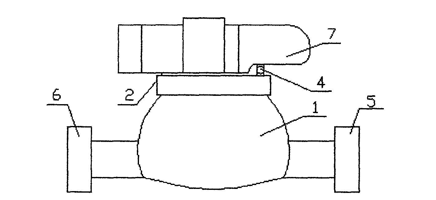
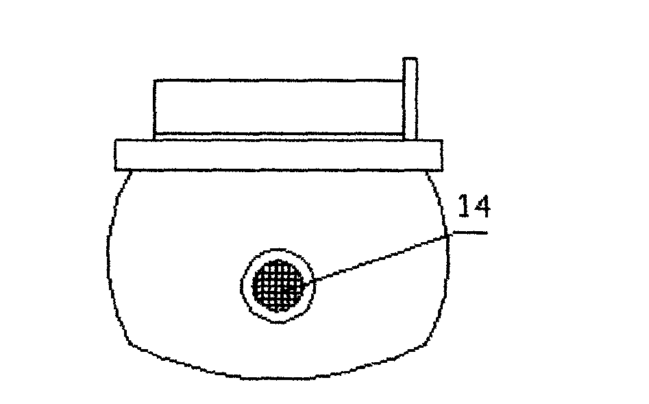
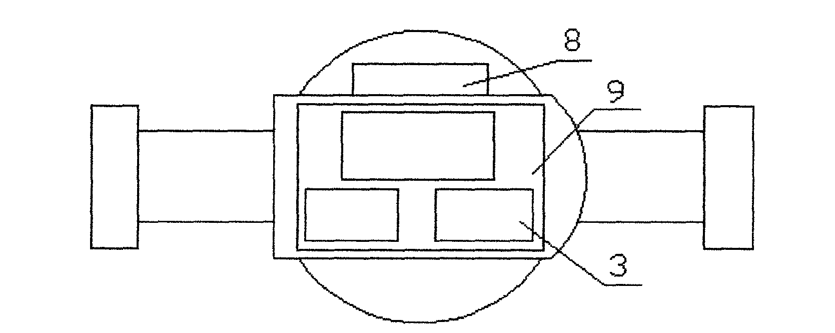
[0021] like figure 1 , figure 2 , image 3 , Figure 4 and Figure 5 As shown, a heat flowmeter of the present invention includes a meter body 1, a round cover 2, an electronic reader 3, a hinge fulcrum 4, an inlet 5, an outlet 6, a liquid crystal display 7 and a magnetic card sensor 8; it is characterized in that: A circuit board 9 is arranged in the meter body, and the circuit board 9 is composed of a temperature input circuit 10, a flow pulse input circuit 11, a liquid crystal display circuit 12 and an electronic control circuit 13, and a valve 15 arranged inside the meter body 1, And the push device 16 arranged inside the valve body, the electronic reader 3 is installed in the liquid crystal display 7, the liquid crystal display 7 and the round cover 2 are installed on the upper end of the watch body 1 through the hinge 4, and the inlet 5 and outlet 6 are respectively installed on both sides of the meter body 1, the magnetic card sensor 8 is installed on the inner sid...


PUM


Abstract

The invention relates to a heat flow meter which comprises a meter body, a circular cover, an electronic reader, a hinge fulcrum, an inlet, an outlet, a liquid crystal display and a magcard inductor. A circuit board is arranged in the meter body and composed of a temperature input circuit, a flow pulse input circuit, a liquid crystal display circuit and an electronic control line, a valve is arranged in the meter body, a pushing device is arranged in a valve body, the electronic reader is installed in the liquid crystal display, the liquid crystal display and the circular cover are installed on the meter body in a matching mode through the hinge fulcrum, and the inlet and the outlet are installed on two sides of the meter body respectively. During usage, a magcard is placed at the position of the magcard inductor, the electronic control line is used for transmitting information to each circuit to open the valve of the heat flow meter, and heat gas flow, temperatures and remaining sum in the magcard can be read from the liquid crystal display. The heat flow meter is simple in structure, accurate in measuring, convenient to use and install, simple in operation, labor-saving, energy-saving, safe and reliable.

Description

technical field [0001] The invention relates to a heat flow meter. Background technique [0002] The current heat flow meters are relatively single, and they are all mechanical movable parts, which are easy to corrode, have a short life, are extremely unstable, and require a lot of maintenance for long-term operation. They are all old-fashioned meters, although they all have electronic Reading tables, but all need to manually record the usage, manual input, bring a lot of inconvenience to the maintenance and recorders, and it is time-consuming and labor-intensive, which brings a lot of inconvenience to people. Contents of the invention [0003] The technical problem to be solved by the present invention is to provide a heat flow meter with simple structure, accurate measurement, convenient use and installation, simple operation, labor saving, safety and reliability. [0004] In order to solve the above problems, the present invention adopts the following technical solutio...

Claims


Application Information

Patent Timeline
IPC IPC(8): G07F15/06
Inventor 黄忠谌述昌
Owner NINGBO YONGGANG INSTR
Learn More