LED (Light-Emitting Diode) constant-current source

A technology of constant current source and LED lamp, which is applied in the direction of light source, electric light source, lighting device, etc., can solve the problem of heat dissipation of LED lamp T2, and achieve the effect of solving heat dissipation difficulty, reducing power consumption, and realizing heat dissipation

Inactive Publication Date: 2013-02-20
GUANGDONG VTRON TECH CO LTD
View PDF6 Cites 3 Cited by
  • Summary
  • Abstract
  • Description
  • Claims
  • Application Information

AI Technical Summary

Problems solved by technology

[0005] The embodiment of the present invention provides an LED constant current source, which can solve the problem of difficult heat dissipation on the LED lamp T2

Method used


Image

  • LED (Light-Emitting Diode) constant-current source
  • LED (Light-Emitting Diode) constant-current source

Examples


Embodiment Construction

[0034] An embodiment of the present invention provides an LED constant current source, which is used to effectively solve the problem of difficult heat dissipation on the LED lamp T2.

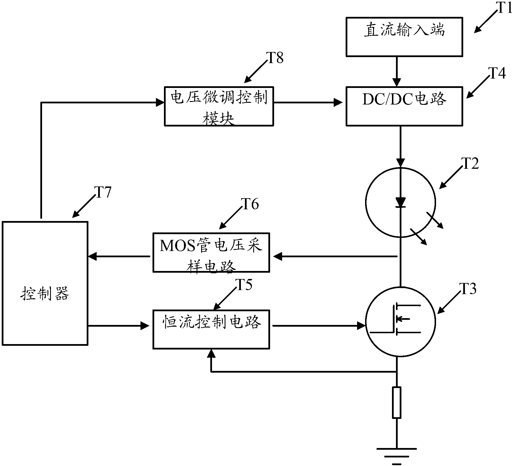
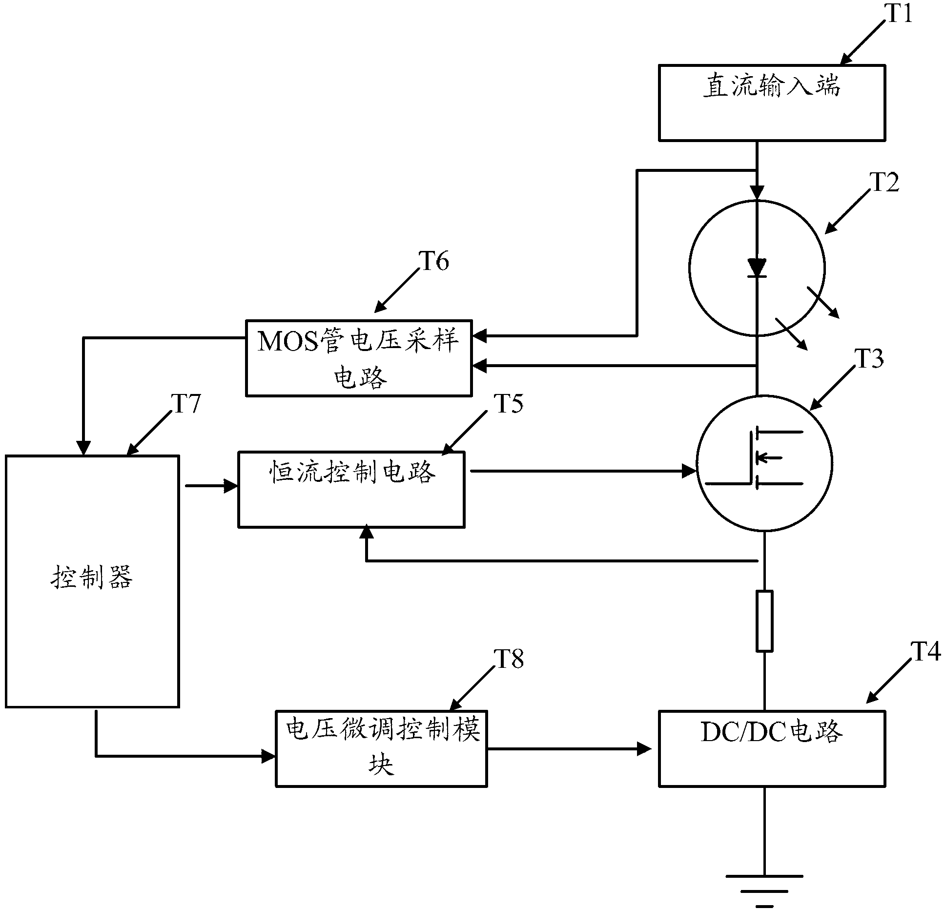
[0035] see figure 2 , the embodiment of the LED constant current source provided by the present invention includes:

[0036] DC input terminal T1, LED lamp T2, MOS tube T3, DC / DC circuit T4, constant current control circuit T5, controller T7, voltage fine-tuning control module T8;

[0037] The DC input terminal T1 is connected to the LED lamp T2, and the LED lamp T2, the MOS tube T3 and the DC / DC circuit T4 are connected in sequence;

[0038] The MOS transistor T3 is connected to one end of the DC / DC circuit T4, and the other end of the DC / DC circuit T4 is grounded;

[0039] The controller T7 is connected to the MOS transistor T3 through the constant current control circuit T5, and the voltage fine-tuning control module T8 is connected to the DC / DC circuit T4;

[0040] The controller T7 is ...


PUM


Abstract

The embodiment of the invention discloses an LED (Light-Emitting Diode) constant-current source which is used for solving the problem that heat of an LED lamp T2 is difficult to radiate. The LED constant-current source provided by the embodiment of the invention comprises a direct-current input end T1, the LED lamp T2, an MOS (Metal Oxide Semiconductor) tube T3, a DC (Direct-Current)/DC circuit T4, a constant-current control circuit T5, a controller T7 and a voltage fine turning control module T8, wherein the direct-current input end T1 is connected with the LED lamp T2; the LED lamp T2, the MOS tube T3 and the DC/DC circuit T4 are sequentially connected; the MOS tube T3 is connected with one end of the DC/DC circuit T4; the other end of the DC/DC circuit T4 is grounded; the controller T7 is connected with the MOS tube T3 through the constant-current control circuit T5; and the voltage fine turning control module T8 is connected with the DC/DC circuit T4. With the adoption of the LED constant-current source provided by the invention, the problem that the heat of the LED lamp T2 is difficult to radiate can be effectively solved.

Description

technical field [0001] The invention relates to the field of electronic circuit machines, in particular to an LED constant current source. Background technique [0002] LED has the advantages of environmental protection, energy saving, and long life, so it is regarded as a lighting source in the 21st century. It has gradually replaced traditional light sources and is widely used in various lighting fixtures. In the projector industry, LEDs are also gradually applied and replace existing UHP bulbs as a new generation of light sources. [0003] see figure 1 , the drive circuit used by the existing LED projector includes: DC input terminal T1, LED lamp T2, MOS tube T3, DC / DC circuit T4, constant current control circuit T5, MOS tube voltage sampling circuit T6, controller T7, voltage trimming Control module T8; the DC input terminal T1 is connected to the DC / DC circuit T4, the DC / DC circuit T4 is connected to the LED lamp T2 and the MOS tube T3 in turn, the MOS tube T3 is grou...

Claims


Application Information

Patent Timeline
Patent Type & Authority Applications(China)
IPC IPC(8): H05B37/02
Inventor 郑维赖增茀梁红涛
Owner GUANGDONG VTRON TECH CO LTD
Why Eureka
Try Eureka